Pressure and temperature gauge switches
Of the total number of all primary measuring transducers produced at that time by the instrument industry, 24%, i.e. the largest number, are pressure measuring instruments... For a comparison of thermometers and pyrometers, according to the same data, 14.5% are produced, and electrical measuring devices - only 6%.
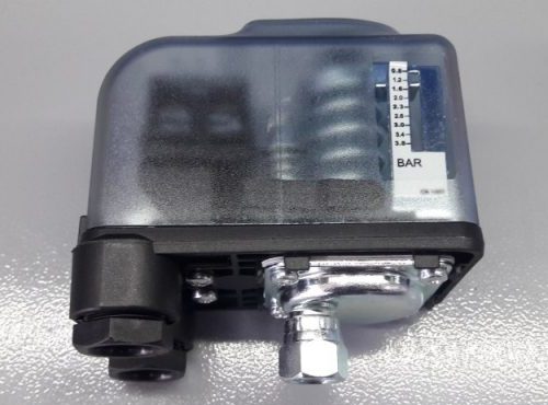
Manometric relays are pressure regulators. They are used to control various installations depending on the pressure in the liquid or gas system. Usually, such a relay consists of a membrane that captures the pressure, a piston with a spring and a switch with electrical contacts.
Purpose, classification and principle of action
Pressure switches are designed for automatic control of electric drives of pumps, compressors and other devices, and some of them also for signaling the limit values of the pressure of liquids and gases in tanks and pipelines.
Manometric relays are produced in two types:
-
single - with one contact system, adjustable to open the controlled circuit at a given maximum pressure in the system;
-
double — representing two independently operating single relays mounted on a common housing. One of these relays is adjusted to close or open the controlled circuit at the lower and the other at the upper pressure set point.
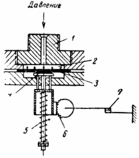
Rice. 1. Kinematic diagram of the pressure switch
The principle of operation of the relay is as follows: the relay is connected to the controlled system through connector 1. The pressure that exists in this system is transmitted through the opening of the fitting into the working cavity 2 and is perceived by the rubber membrane 3, which at the same time prevents the penetration of liquid or gas in the relay housing.
The membrane transfers the perceived pressure to the metal piston 4, the movement of which is prevented by the spring 5, adjusted to a given pressure. When the pressure on the piston exceeds the opposite pressure of the spring, the piston will go down and with the help of the gear (or lever) of the transmission 6 will open the contacts of the relay.
Brief description of the construction of the relay type RM-52/2.
Relay RM-52/2 is a single relay (the kinematic diagram is shown in Fig. 3), consisting of the following four structural units:
1) node that perceives the pressure;
2) gearbox;
3) contact system;
4) regulating device.
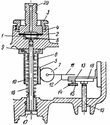
Rice. 2. Kinematic diagram of manometric single relay type RM-52/2
The pressure receiving unit consists of a metal piston 1 and a membrane 2, pressed to the body 4 with a nut 3. The connection between the pressure receiving unit and a gear consisting of a rack 5 attached to a glass 6 and a gear 7 is carried out by means of columns, one end adjacent to the base of the piston, and others resting on the movable sleeve 9.The cup 6 and the sleeve 9 are able to move freely along the rod 10.
The contact system consists of an armature 11 attached to the axis of the gear wheel 7, a contact spring 12 attached to the armature, a movable contact 12 in a fixed contact 14 attached to an insulating block 15. The regulating device consists of a spring 16 placed on a rod 10 , plug 17, magnet 18 and screw 19.
Installation information
Before installing the relay, it is necessary to adjust the pressure, for which:
-
connect the relay through fitting 20 to the controlled system;
-
unscrewing screw 19, the magnet is slightly lowered;
-
smooth screwing of the plug 17, slightly pressing the spring;
-
set the pressure in the system at which the contacts should open (the pressure is checked by the manometer) and be supplied through the fitting to the relay;
-
if at this pressure the contacts do not open, the magnet is raised by screwing the screw 19 in the box; if the contacts open before the applied pressure reaches a predetermined value, the magnet is lowered.
If the adjustment by the magnet does not give the desired effect, it must be done by a combination of changing the position of the magnet and the compression force of the spring. After adjusting the pressure, connect it to the system, insert and connect the cable.
Dual pressure switches
Two-rail relays consist of three main structural units:
-
node that directly perceives pressure;
-
contact system;
-
regulating device.
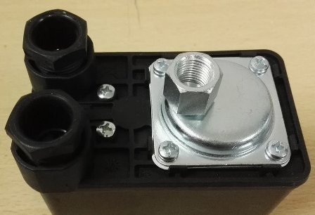
The pressure receiving unit consists of two pistons and a diaphragm. The diaphragms together with the rings and the joint are fixed with screws in a metal casting on which the relay is mounted.The connection between the pressure receiving unit and the contact system is made through columns and a system of levers. The columns are firmly connected to the pistons at one end and rest against the cushions at the other.
The contact system consists of a fixed contact fixed on an insulating tape, which in turn is fixed on a metal square lying on the casting, and a movable contact located on a contact plate fixed on an insulating tape. To reliably close the contacts, the contact plate is equipped with a pressure spring, and to prevent burning of the contacts, capacitors are connected in parallel with the contacts.
The presence of two contact and control systems allows you to adjust the relay to two pressure settings — the lower one, which turns on the electric motor when the pressure drops to a predetermined minimum (adjustment is carried out by a spring), and the upper one, which turns off the electric motor when the pressure rise to a predetermined maximum.
Brief description of the construction of the RDE type relay
The RDE type relay belongs to double relays and in its design (the kinematic diagram is shown in Fig. 3) differs from the PM relay described above, mainly in the design of the contact system. The contact system of the relay, unlike those described above, consists of two micro switches (keys) of the MP-1 type, the contacts of which are in a carbolite box. Relay version — waterproof.
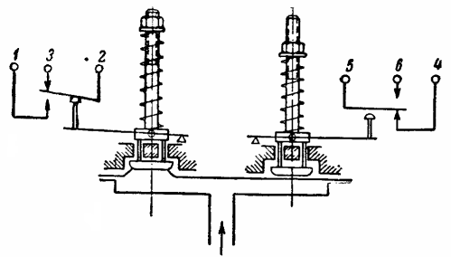
Rice. 3. Kinematic diagram of a double-relay relay type RDE
Kinematic diagram of a double relay type RDE.
The relay can also be used to signal when pressure limits have been reached.In this case, if the difference between the on and off pressure values does not exceed 0.2 kg / cm2, usually only one microswitch is used, and with a pressure difference of more than 0.2 kg / cm2, — both microswitches, one for signaling when the lower pressure limit is reached and the other for the upper pressure limit.
Pressure gauge temperature switches
EKT type electronic thermometer
Instruments of this type are usually produced on the basis of a single-block pressostat.
To do this, the bellows box is connected through a capillary tube to a thermocylinder filled with a low-boiling liquid or gas with a solid adsorbent. As the temperature increases, the pressure in the closed system (thermocylinder — pipe — sleeve) increases and is transmitted to the lever mechanism of the relay.
Their sensing element is a thermocylinder filled with liquid (for EKT-1) or gas (for EKT-2) and connected via a capillary tube to a tubular manometer spring. EKT, like EKM, is a three-position relay.
The opening temperature range depends on the filler:
-
with carbon dioxide from -60 to 0 ° C;
-
with freon -12 from -20 to 40 ° C;
-
with chloromethyl 0-60 and 0-100;
-
with benzene 50 — 150, 60 — 200 and 100 — 250;
-
with gaseous nitrogen 0 — 300 and 0 — 400 ° C.
The total differential is adjusted within the scale. Partial differential is 0.5 °C. Basic error is 2.5% of range. The breaking capacity of the contacts is 10 VA. Capillary length from 1.6 to 10 m.
Temperature relay type TP
The construction of the TP-1 and TP-1B relays is similar to the RD-1B pressure switch. Unlike the TR-1B temperature relay TR-2B, a rise in temperature causes the contacts to open.Relays of this type are also produced in an explosion-proof design (TP-1BM) and in a marine design (TP-5M). The TR-5M relay has a changeover contact with three output terminals. Its thermocylinder can be smooth (for liquid media) or finned (for air).
The TP-2A-06ТM relay is designed to shut down freon and ammonia compressors in the event of a dangerous increase in discharge temperature. May be used in Class B-16 hazardous areas. It has a nautical and tropical design. The breaking capacity of the contacts at an alternating voltage of 220 V is 300 V A.