Microprocessor meters INF-200 and IS-10
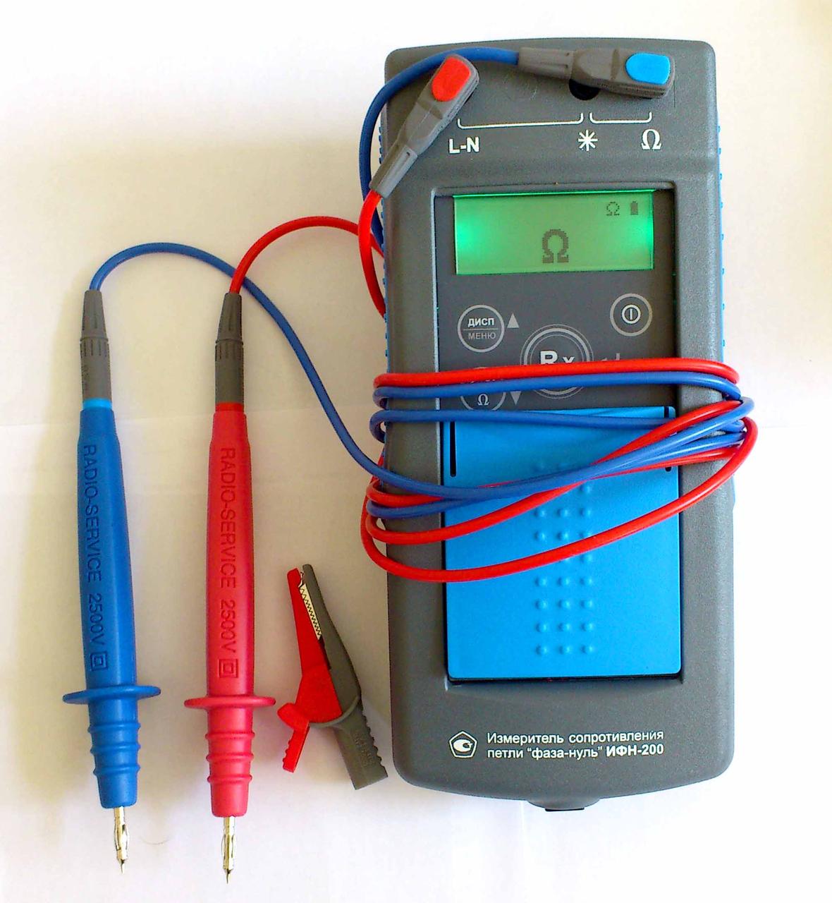
Various types of resistance meters are used in the power industry: microohmmeters, milliohmmeters, ohmmeters, megohmmeters, impedance meters, etc. This article discusses: the IFN-200 «phase zero» loop resistance meter and the IS-10 earth resistance meter.
The «phase zero» loop resistance meter is a device for measuring the resistance of an electrical network directly under voltage.
The IFN-200 device performs the following functions:
-
measurement of the total, active and reactive resistance of the phase-zero circuit without disconnecting the power source with a nominal voltage of 220 V;
-
AC voltage measurement;
-
DC resistance measurement (ohmmeter mode);
-
measuring the resistance of a metal connection with a current of up to 250 mA for resistances <20 Ohm;
-
calculation of the expected short-circuit current at the connection point of the device.
The «phase zero» circuit is a section of the network from the secondary winding of a power transformer to an electrical receiver.Such a section of the network can be represented in the form of an equivalent circuit consisting of an alternating voltage source Uc and resistances Rc and Xc, as shown in Fig. 1.
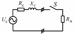
Rice. 1. Equivalent network circuit with the connected IFN-200 device
First, the device IFN-200 with an open switch S (see Fig. 1) measures the value of the amplitude and phase of the voltage Uc. The switch S is then closed for 25 ms, connecting the load Rn = 10 Ohm to the network. In this case, the value of the amplitude and phase of the load current In is measured. The result is a system of two equations:
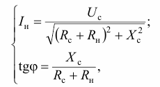
where j is the phase difference between the voltage Uc and the current In.
After solving the system, expressions for Rc and Xc can be obtained. These expressions are used by the device software.
The values of Rc and Xc can be used to judge the quality of the wiring as well as for the correct selection of circuit breakers.
The quality of wiring in the electrical network is questionable when Rc> 0.5 Ohm; Xc> 1 ohm. The main reason for this situation is an increase in contact resistance in switchboards, junction boxes and contacts. The correctness of the breaker selection can be checked by the condition
Iem.r < Ikz,
where Iem.r — operational current of the electromagnetic release of the breaker; Isc — rated short-circuit current.
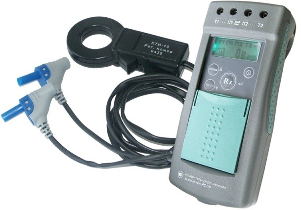
The IS-10 device is designed to measure the resistance of grounding elements, metal joints and the continuity of protective conductors using the four-wire method. It has a function to automatically calculate soil resistance.Using a current clamp, the device measures the alternating current in the grounding electrodes without interrupting the measured circuit, which makes it possible to make a qualitative assessment of their condition.
The «MODE» button is used to switch the device to the modes of two-, three- and four-wire measurement methods, measurements with automatic calculation of soil resistance and work with clamps for measuring current or determining the percentage distribution of currents. When entering the «MENU» mode, this button performs the function of moving up through the menu.
The «MENU» button is used to switch the device into parameter setting mode. After entering the «MENU» button performs the function of moving down the menu. Earth loop resistance measurement range: 1 mOhm to 10 kOhm.
The functional diagram of the earthing resistance measurement by the four-wire method is shown in Fig. 2.
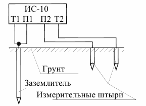
Rice. 2. Circuit for measuring earthing resistance by four-wire method
The device has current outputs T1 and T2 as well as potential inputs P1 and P2. Through the outputs T1 and T2, it forms a measuring stabilized pulse current with variable polarity (meander) with a frequency of 128 Hz. The peak value of the current strength is no more than 260 mA, the maximum peak value of the output voltage without load is no more than 42 V. The voltage drop in the measured circuit at stabilized current is proportional to its resistance.
This voltage is measured across inputs P1 and P2, filtered and fed to the input amplifier and then to the ADC.The binary codes generated by the ADC are passed to the microcontroller where the required values are calculated and displayed on the display. The connection to the ground wires is made using special probes and clamps, and the connection to the ground is made using 1 m long submerged metal pins.
The procedure for determining earth resistance using the four-wire method is as follows:
1. Determine the maximum diagonal D of the grounding device (ZU).
2. Connect the charger using test leads to sockets T1 and P1.
3. Potential pin P2 placed in the ground at a distance of 1.5D, but not less than 20 m from the measured grounding device.
4. Place the current pin T2 in the ground at a distance of more than 3 D, but not less than 40 m from the grounding device. Connect the connecting cable to the T2 connector on the device. Carry out a series of earth resistance measurements by successively mounting the potential pin P2 into the ground at distances of 10, 20, 30, 40, 50, 60, 70, 80 and 90% of the distance to the current pin T2 using the four-wire method.
5. Plot the dependence of the resistance on the distance between the grounding device and the potential pin P2. If the curve increases monotonically and has a fairly horizontal section in the middle part (at distances 40 and 60%, the difference in resistance values is less than 10%), then the resistance value at a distance of 50% is taken as true. Otherwise, all distances to the pins must be increased by 1.5-2 times or the direction of installation of the pins must be changed to reduce the influence of aerial or underground communications.
The scheme for determining soil resistance using the IS-10 device is shown in Fig. 3.
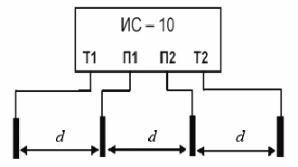
Rice. 3. Scheme for determining soil resistance
The soil resistivity value is calculated according to Werner's measurement method. This technique implies equal distances between the electrodes d, which must be taken at least 5 times greater than the depth of immersion of the pins.
The measuring pins are installed in the ground in a straight line, at equal distances d, and are connected to the measuring sockets T1, P1, P2 and T2, selecting the mode of the four-wire measurement method.
Then you need to press "Rx", Read the readings of the resistance value RE.
Soil resistance is calculated using the formula: