Determining types and locations of cable line faults using OTDR
An OTDR is a microprocessor-based device that allows you to determine the distance to the locations of faults and irregularities in power lines, as well as the nature of these faults and irregularities.
The principle of operation of the reflectometer is based on the generation of a short probing voltage pulse in the cable core and the reception of the pulse reflected from the location of the damage (effect of incident and reflected waves in lines with distributed parameters). The device determines the distance Lx to the fault during the time interval tx between the probing and reflected pulses by the formula:
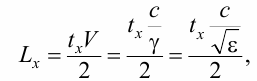
where V is the velocity of wave propagation along the line; c is the speed of light; y is the truncation factor; e is the relative dielectric constant.
The shortening factor y shows how many times the speed of propagation of the pulse in the line is less than the speed of its propagation in the air.
The accuracy of determining the distance to the location of the damage depends on the chosen value of the shortening factor.
For some types of cables, the value of the shortening factor is known. In the absence of these data, it can be determined experimentally if the length of the cable is known. The reflected pulse appears at those places on the line where the characteristic impedance deviates from its average value: at the connectors, at the places where the cross-section changes, at the places where the cable is compressed, at the leakage point, at the break point, at the short circuit point, at the end of the cable and others.
At the places where the device is connected, reflections also occur from the output impedance of the probe pulse generator if it is not equal to the average wave impedance of the line. Therefore, the operation of matching the output impedance of the generator with the characteristic impedance of the line should be performed smoothly.
The attenuation of probing pulses in the line significantly affects the reflected signal and depends on its geometric design, conductor material and insulation. The consequence of this is a decrease in the amplitude and an increase in the duration of the reflected pulses and, accordingly, a decrease in the accuracy of determining the distance to the location of the damage.
To eliminate the influence of attenuation, it is necessary to choose the parameters (amplitude and duration) of the probe pulse in such a way that the amplitude of the reflected pulse is maximal and its duration is minimal. The absence of a reflected signal indicates the exact match of the system to the line in terms of characteristic impedance and the absence of faults.
In the event of a break, the reflected pulse has the same polarity as the probe. In the case of a short circuit, the reflected pulse reverses its polarity.
The biggest difficulty in the pulse reflectometry method is separating the useful signal from the noise.
According to the ratio of reflected signal and interference levels, line damage can be divided into simple and complex.
A simple fault is such a cable line fault where the amplitude of the reflection from the fault location is greater than the amplitude of the disturbance.
Complex damage is such damage to a cable line where the amplitude of reflection from the location of the damage is comparable to the amplitude of interference.
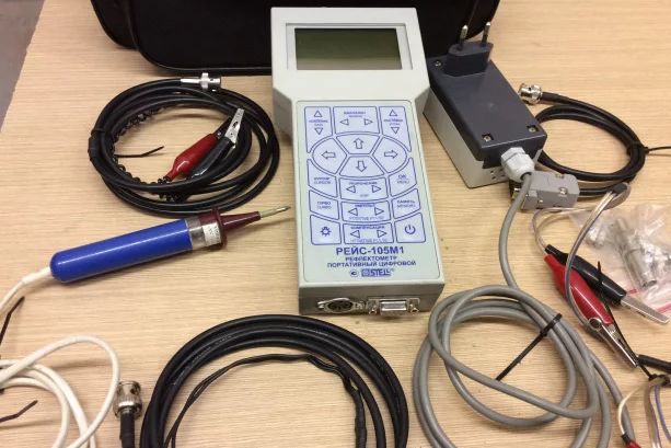
As a rule, complex injuries occur much more often than simple ones. The external view of the REIS-105M1 reflectometer is shown in fig. 1.
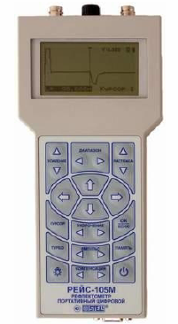
Rice 1. External view of the REIS-105M1 reflectometer
The main functions of the device:
-
entering a shortening factor;
-
display of reflectograms on the display;
-
calculating the distance to the place of reflection of the probing pulse in the investigated line in accordance with the position of the cursors set by the user;
-
programmable signal gain;
-
recording of reflexograms in memory;
-
transmission of reflectograms to a computer via RS232 interface.