Circuit Topologies—Basic Concepts
An electrical circuit is a set of devices (elements) and their connecting wires through which an electric current can flow. All elements of electric circuits share in passive and active.
Active elements convert different types of energy (mechanical, chemical, light, etc.) into electrical energy. In passive devices, electrical energy is converted into other types of energy. Active elements are called sources, passive ones are called consumers or receivers.
In circuit theory, idealized models of electrical elements are considered. This makes the description of the elements as simple as possible. More complex, real elements are modeled from a set of idealized elements.
The main passive elements of electric circuits are resistor (resistive element), inductor (inductive element) and capacitor (capacitive element). Elements are installed in an electric circuit to generate voltage and current of a given value and shape (see — Electric circuit and its elements).

An electrical circuit consists of branches and nodes. Branch — this is a section of an electrical circuit (circuit) through which the same current flows. A node — connection of three or more branches. On the electrical diagram, the node is indicated by a dot (Fig. 1).
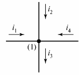
Rice. 1. Define the node in the diagram
If necessary, the nodes of the diagram are numbered from left to right from top to bottom.
In fig. 2 shows the resistive-capacitive branch in which the current iC flows.
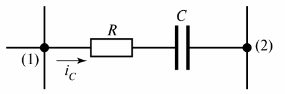
Rice. 2. Resistive-capacitive branch
Another definition of a branch can be given — it is a section of a circuit between two adjacent nodes (nodes (1) and (2) in Fig. 2).
Chain Is there any closed path in the electrical circuit. The circuit can be closed by any branches, including conditional branches whose resistance is equal to infinity.
In fig. 3 shows a branched electrical circuit that consists of three branches.
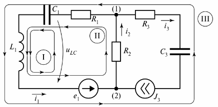
Rice. 3. Electric circuit with two circuits
The diagram shows three circuits, and circuit I is closed by a branch of infinite resistance. This branch is indicated as voltage tiLC.
For the circuit of Fig. 3 it is possible to compose many loops that are closed by real or conditional branches, but for the calculation of electrical noise the concept of «independent loop» is used. The number of independent circuit loops is always set as the minimum required for the calculation.
Independent circuits are always closed, but branches that have a resistance not equal to infinity, and each independent circuit includes at least one branch that is not included in other circuits. For complex electrical circuits, you can determine the number of independent circuits using the circuit diagram.
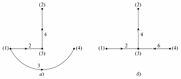
On the circuit diagram a conditional representation of the circuit is called, in which each branch is replaced by a line segment. Items in branches are not displayed. For example, in FIG. 4 shows a branch circuit and its diagram.
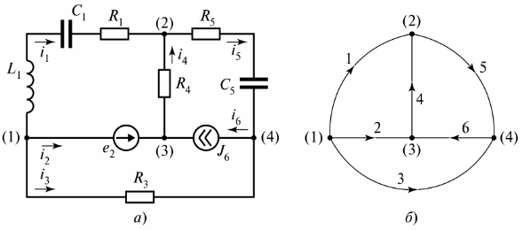
Rice. 4. Branched electric circuit: a — circuit diagram, b — diagram
To make a diagram of a diagram, you must connect the nodes with branch lines without specifying elements on them. The branches are numbered, and the directions of the currents on them are indicated by arrows. The graph itself has no physical meaning, but can be used to determine the number and type of independent contours. For this purpose, a "graphic tree" is prepared.
Graphic tree It represents the graph of a circuit whose nodes are connected by branches in such a way that no closed loop results. There may be several options for displaying a graphical tree. In fig. 5 shows two possible options for the circuit of FIG. 4.
Rice. 5. Graphic tree of the scheme
The number of missing branches in the graph tree is equal to the number of independent loops of the chain. In the example, these are three branches, three independent loops. The configuration of independent loops can be obtained by sequentially connecting the nodes of the graph tree with branches that are not specified on the graph tree. For example, for the graph tree in Fig. 5, and the independent contours are shown in fig. 6.
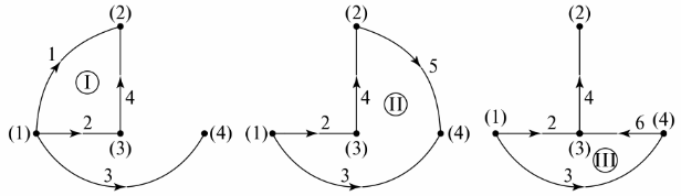
Rice. 6. Determining independent contours through the graph tree
The selection of an option to configure independent circuits for calculating the circuit is carried out during circuit analysis. You should choose such contours so that the calculation is as simple as possible, i.e. the number of dependent equations in the system is minimal.
Topological equations establish a relationship between voltages and currents in a circuit, and the number and type of equations do not depend on which elements are included in the branches. Topological equations include equations composed of according to Kirchhoff's laws.