Electromagnetic braking devices
In some devices, an electromagnetic disc brake on an electric motor is used to stop the rotating elements of the machine. The electromagnetic braking device is mounted directly in the motor or on the motor and is essentially an auxiliary motor or drive unit that meets all the requirements both in terms of the positioning of the device and in terms of its safe operation. It is applied and released with a spring with an electromagnet.
This solution allows not only to ensure a safe stop of the engine in case of an accident or to position the executive element of the machine during its operation, but also simply reduces the time of operation of the machine during its stop.
There are two types of electromagnetic disc brakes: AC disc brakes and DC disc brakes (depending on the form of current that powers the brake). For the DC version of the brake, a rectifier is also supplied to the motor, through which the DC is obtained from the AC that powers the motor itself.
The design of the braking device includes: electromagnet, armature and disc. The electromagnet is made in the form of a set of coils located in a special case. The armature serves as a braking mechanism and is an anti-friction surface that interacts with the brake disc.
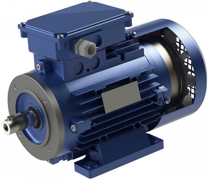
The disc itself, with the friction material applied to it, moves along the teeth of the sleeve on the motor shaft. When voltage is applied to the brake coils, the armature is pulled and the motor shaft can rotate freely with the brake disc.
Braking is provided in the free state when the springs press the armature and it acts on the brake disc, thus stopping the shaft.
Brakes of this type are widely used in electric drive systems. In the event of an emergency power failure to the braking device, it may be possible to manually release the brake.
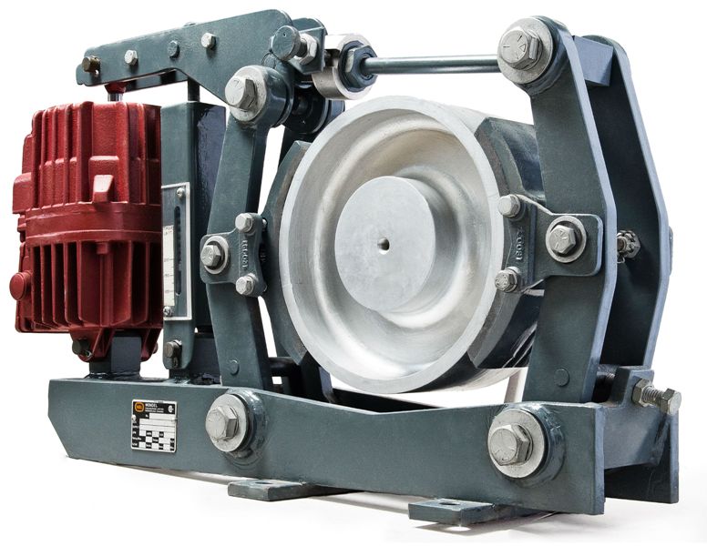
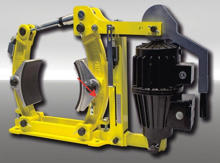
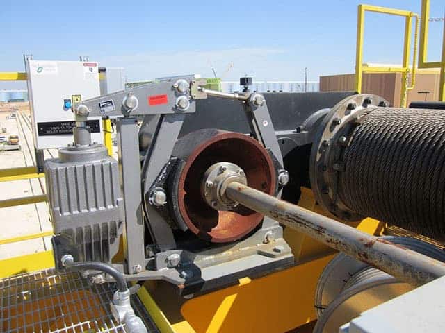
Hoists use an electromagnetic shoe brake (TKG) to hold the shaft in a braked state when the machine is off.
TKP — MP series DC brake. TKG - electro-hydraulic tappet brake, TE series. The TKG brake solenoid includes a drive and mechanical part, which in turn includes: a stand, springs, a lever system and brake pads.
The brake unit is mounted vertically with the brake disc in a horizontal position. The mechanical parts of AC or DC powered braking devices are the same for rollers of the same diameter.
Usually, such devices have the letter designation TK and a number indicating the diameter of the brake roller. When the power is turned on, the levers neutralize the action of the springs and release the pulley to allow free rotation.
Electromagnetic brakes are used in:
-
blocking of cranes, elevators, laying machines, etc. in the off state; in mechanisms for stopping conveyors, winding and weaving machines, valves, mobile equipment, etc.;
-
to reduce downtime (downtime during shutdown) of machines;
-
in emergency stop systems for escalators, agitators, etc., etc.;
-
to stop with positioning the exact position at a certain point in time.
In drilling platforms, induction braking is used, based on the interaction of the magnetic fields of an inductor, in the role of which an electromagnet acts, and an armature, in the coil of which currents are induced, the magnetic fields of which slow down "the cause that causes them" (see Lenz's law), thus creating the necessary braking torque for the rotor.
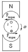
Let's look at this phenomenon in the figure. When current is switched on in the stator winding, its magnetic field induces an eddy current in the rotor. The eddy current in the rotor is affected by Ampere's force, the moment of which in this case slows down.
As you know, asynchronous and synchronous machines with alternating current, as well as machines with direct current, when the shaft moves relative to the stator, can work in the braking mode. If the shaft is stationary (no relative motion), there will be no braking effect.
Thus, motor-based brakes are used to stop moving shafts rather than holding them at rest. At the same time, the intensity of deceleration of the movement of the mechanism can be adjusted smoothly in such cases, which is sometimes convenient.
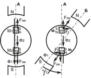
The following figure shows the operation of the hysteresis brake.When a current is supplied to the stator winding, the torque acts on the rotor, in this case it stops and occurs here due to the phenomenon of hysteresis from the reversal of the magnetization of a monolithic rotor.
The physical reason is that the magnetization of the rotor becomes such that its magnetic flux coincides in direction with the stator flux. And if you try to rotate the rotor from this position (so that the stator is in position B relative to the rotor), it will try to return to position A due to the tangential components of the magnetic forces—and this is how braking occurs in this case.