Measuring instrument — vernier, micrometer, metal compass and metal ruler
The main measuring tools in the process of carrying out repair work are a vernier, a micrometer, a pair of compasses for metal and a metal ruler.
Caliper device
With the help of a caliper, linear quantities are measured with an accuracy of up to a tenth of a millimeter. As you can see from the figure, the vernier is a universal device that allows you to measure the external and internal dimensions of parts, as well as the dimensions of recesses.
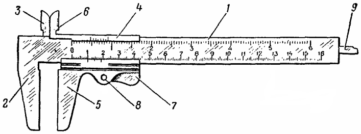
Rice. 1. Vernier: 1 — metric ruler, 2, 3 — fixed jaws, 4 — slider, 5, 6 — movable jaws, 7 — stopper, 8 — stopper axis, 9 — ruler.
It consists of a bar in the form of a metric ruler 1 with fixed jaws 2 and 3 and a slider 4 with movable jaws 5 and 6. On the reverse side of the metric ruler there is a longitudinal groove in which a narrower ruler 9 with a width of 4 — 5 is located mm, firmly fixed with a slider 4. So, when you move the slider along the metric ruler 1, the ruler 9 goes to the corresponding value beyond the end of the metric ruler.
In order to fix the position of the slider 4 during the measurement, it has a spring brake, which is released by pressing the plug 7 (in some designs of the calipers, a screw is installed instead of the plug, which fixes the position of the vernier frame). On the engine 4 there is an inclined cut on which the vernier is applied.
Vernier (Fig. 2) is a scale 9 mm long, divided into 10 parts, 0.9 mm each. In the extreme left position of the slide of the caliper, its jaws should fit tightly together, while the ends of the metric and narrow rulers should be on the same line, and the zero division of the metric ruler should coincide with the first line of the vernier ( while the tenth part of the vernier scale should coincide with the ninth scale of the division).
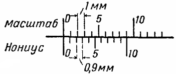
Rice. 2. The ratio of the divisions of the vernier and the scale of the metric ruler
How to use a caliper
For measurement, the part is placed between the jaws of the caliper. Moving the slider, it is necessary to reduce the jaws to a tight fit to the surface of the measured part. The size is counted per caliper in the following order:
- the position of the first risks of the vernier is determined relative to the division of the metric ruler;
- determine which risk of the vernier coincides with the risk of (any) metric rulers;
- the reading is done by adding the two readings.
Example (Fig. 3, a). The zero risk of the vernier is between the 31st and 32nd divisions of the metric ruler, and its fourth risk coincides with some risk on the ruler. In this case, the measured value will be 31.4 mm. What are the caliper readings given in the examples in fig. 3, b and c?
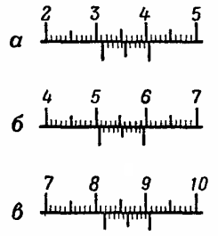
Rice. 3. Examples of counting caliper readings
Answer: b — 50.8 mm; h — 81.9 mm.
The vernier must be protected from impact, mechanical stress and lubricated with a thin layer of machine oil to prevent corrosion and seizure of moving parts.
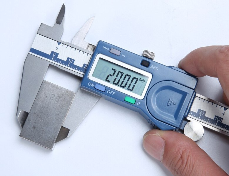
Recently, electronic calipers with a digital readout device have gained widespread popularity. Other types of meters are also discussed here: Caliber - types and examples of use
Micrometer
The micrometer is one of the most common measuring instruments. Figure 4 shows a flat micrometer. It is used for external measurements from 0 to 25 mm with an accuracy of 0.01 mm.
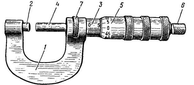
Rice. 4. Micrometer: 1 — bracket; 2 — fifth; 3 — sleeve; 4 — micrometric screw; 5 — drum; 6 — clutch ratchet; 7 — locking device
The micrometer consists of a clip 1 with a heel 2, a sleeve 3 pressed into the clamp, a micrometer screw 4, a drum 5, a ratchet coupling 6 and a locking device 7. A micrometer thread is cut inside the sleeve 3 with a step of 0.5 mm. Drum 5 is fixed on a micrometric screw 4, which also has a thread with a pitch of 0.5 mm. Therefore, with one rotation of the drum 5, the micrometer screw 4 moves in the axial direction by 0.5 mm.
On the front side of the sleeve there is a longitudinal scale with a graduation of 0.5 mm. Around the circumference of the drum 5, on its beveled edge, there is also a scale consisting of 50 divisions evenly distributed along the circumference. Therefore, when the drum is rotated by one division of the scale marked on its circumference, the micrometer screw moves in the axial direction by 0.01 mm.
To measure the workpiece, insert between the ends of the heel 2 micrometer screws 4. Then, turning the micrometer screw with the help of a ratchet coupling, it is necessary to clamp the workpiece between the ends of the micrometer screw and the heel.The compressive force of the workpiece during measurement is limited by the frictional force. In this micrometer, it is equal to 700 +200 g. Therefore, during the measurement process, the workpiece is not deformed and is protected from damage to the micrometer.
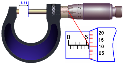
The micrometer readings are counted in the following order. First, the number of millimeters is counted on the scale of the micrometer sleeve (with an accuracy of 0.5 mm) bounded by the end of the drum, then the number of hundredths of a millimeter corresponding to the division of the drum scale located opposite the axis of bushing axis.
An example. On the sleeve scale, the number 15, a half millimeter division, and part of the subsequent half millimeter division, the 13th division of the drum scale coincides with the axial line of the sleeve scale, therefore the size of the part is 15.5 + 0.13 = 15 .63 mm.
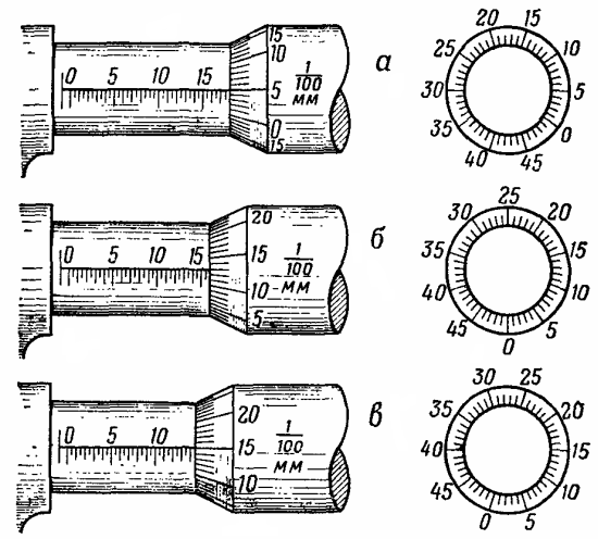
Rice. 5. Examples of micrometer readings: a — 17.55 mm; b — 15.63 mm; h — 14.15 mm
The ends of the micrometer screw and the heel of the micrometer must be protected from shocks and scratches, which will reduce the accuracy of the micrometer readings.
Metal ruler
A metal ruler with an accuracy of 1 — 0.5 mm is used to measure the distance between two points. It is a steel tape graduated in millimeters.
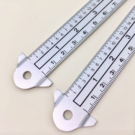
A metal ruler, like any measuring device, should have a manufacturer's stamp. A ruler without a mark should not be used for measurements. It is enough to have a metal ruler with a length of 200 - 500 mm. The ruler should be straight, not jagged, with clearly marked sections.
Compass for metal
A compass for metal is used for marking work, drawing circles on the surface of solid materials and for measurements by the transfer method (by measuring the solution size of the legs of the compass with a metal ruler).
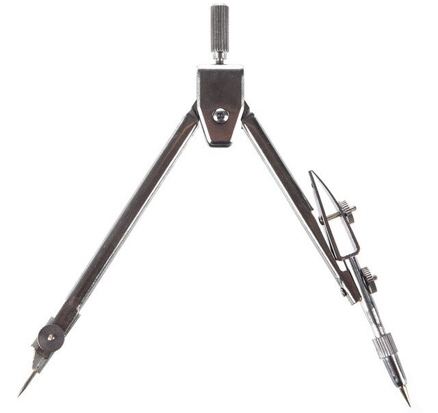
The compass should have pointed and slightly hardened points on the legs. Backlash and damping in the compass joint are unacceptable.