Peak transformers — principle of operation, device, purpose and application
There is a special type of electrical transformer called a peak transformer. A transformer of this type converts the sinusoidal voltage applied to its primary winding into pulses of different polarity and the same frequency as the primary sinusoidal voltage… The sine wave is fed here to the primary winding and the pulses are removed from the secondary winding of the peak transformer.
Peak transformers are used in some cases to control gas discharge devices such as thyratrons and mercury rectifiers, as well as to control semiconductor thyristors and for some other special purposes.

The principle of operation of the peak transformer
The operation of the peak transformer is based on the phenomenon of magnetic saturation of the ferromagnetic material of its core. The conclusion is that the value of the magnetic induction B in the magnetized ferromagnetic core of the transformer nonlinearly depends on the strength of the magnetizing field H of the given ferromagnet.
Thus, at low values of the magnetizing field H — the induction B in the core first rapidly and almost linearly increases, but the greater the magnetizing field H, the more slowly the induction B in the core continues to grow.
And eventually, with a sufficiently strong magnetizing field, the induction B practically stops increasing, although the intensity H of the magnetizing field continues to increase. This nonlinear dependence of B on H is characterized by the so-called hysteresis loop.
It is known that the magnetic flux F, the change of which causes the induction of EMF in the secondary winding of the transformer, is equal to the product of the induction B in the core of this winding by the cross-sectional area S of the winding core.
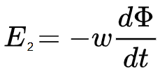
So, in accordance with Faraday's law of electromagnetic induction, the EMF E2 in the secondary winding of the transformer turns out to be proportional to the rate of change of the magnetic flux F penetrating the secondary winding and the number of turns w in it.
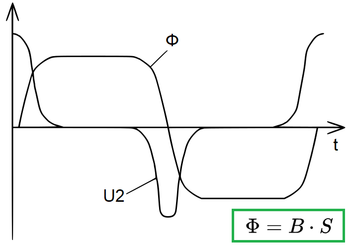
Considering both the above factors, it can be easily understood that with sufficient amplitude to saturate the ferromagnet in the time intervals corresponding to the peaks of the sinusoid of the voltage applied to the primary winding of the peak transformer, the magnetic flux Φ in it the core in these moments will practically not change.
But only near the moments of transitions of the sinusoid of the magnetizing field H through zero, the magnetic flux F in the core will change and quite sharply and quickly (see the figure above).And the narrower the hysteresis loop of the transformer core, the greater its magnetic permeability, and the higher the frequency of the voltage applied to the primary winding of the transformer, the greater the rate of change of the magnetic flux in these moments.
Accordingly, near the moments of transition of the magnetic field of the core H through zero, given that the speed of these transitions is high, short bell-shaped pulses of alternating polarity will form on the secondary winding of the transformer, since the direction of change of the magnetic flux F initiating these pulses also alternates.
Peak transformer device
Peak transformers can be made with a magnetic shunt or with an additional resistor in the supply circuit of the primary winding.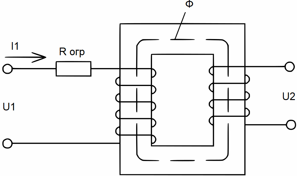
The solution with a resistor in the primary circuit is not much different from a classic transformer... Only here the peak current in the primary winding (consumed in the intervals when the core enters saturation) is limited by a resistor. In designing such a peaking transformer, they are guided by the requirement to provide deep saturation of the core at the peaks of the half-waves of the sine wave.
To do this, select the appropriate parameters of the supply voltage, the value of the resistor, the cross-section of the magnetic circuit and the number of turns in the primary winding of the transformer. In order to make the pulses as short as possible, a magnetically soft material with characteristic high magnetic permeability, for example permaloid, is used for the production of the magnetic circuit.
The amplitude of the received pulses will directly depend on the number of turns in the secondary winding of the finished transformer. The presence of a resistor, of course, causes significant losses of active power in such a design, but it greatly simplifies the design of the core.
A peak current-limiting magnetic shunt transformer is made on a three-stage magnetic circuit, where the third rod is separated from the first two rods by an air gap, and the first and second rods are closed to each other and carry the primary and secondary windings.
When the magnetizing field H increases, the closed magnetic circuit first saturates because its magnetic resistance is less. With a further increase in the magnetizing field, the magnetic flux F is closed through the third rod — the shunt, while reactivity the circuit increases slightly, which limits the peak current.
Compared to a design involving a resistor, the active losses are lower here, although the core construction turns out to be a bit more complicated.
Applications with peak transformers
As you already understood, peak transformers are necessary to obtain short pulses of sinusoidal alternating voltage. The pulses obtained by this method are characterized by a short rise and fall time, which makes it possible to use them to power control electrodes, for example, semiconductor thyristors, vacuum thyratrons, etc.