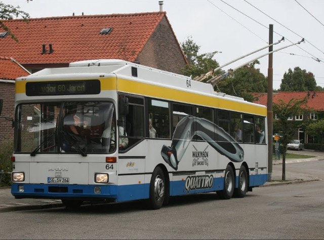
How the trolleybus works and works
Residents of many cities are so used to riding trolleybuses that they hardly think about the fact that at this moment they are using an ecological and quite economical form of transport, something like a multi-seater electric car. Meanwhile, the device of a trolleybus is no less interesting than the device of, say, a tram. Let's dive a little deeper into this topic.
The modern trolleybus has a rather complex electrical part. Its control system is based on semiconductors controlled by a microprocessor, working together with air suspension, ABS system and closely interacting with all parts of the complex electronic information system. This includes the possibility of autonomous movement, microclimate regulation system, etc.
Thus, today's trolleybus is a full-fledged urban public vehicle that meets all requirements for safety, comfort and efficiency.
The evolution of the trolleybus developed gradually, almost in the same way as for buses.It is easy to assume that the body structures of the first trolleybuses and their chassis were originally based on low-floor buses such as Bogdan-E231, MAZ-203T and others. However, the trolleybus itself appeared much later. And such modern city cars as Electron-T191 and AKSM-321, for example, were immediately developed as trolleybuses. But the continuity of the body from model to model can still be traced.
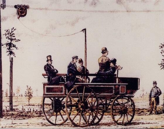
The progenitor of the trolleybus in the late 19th century:
Even from the time of the Soviet Union, this vehicle from the catenary through carts became a custom a constant voltage of 550 volts is supplied… That's the standard. Under these conditions, a fully loaded trolleybus can reach a speed of about 60 km/h on a level road.
Traction drive was originally intended for urban traffic, therefore it limits the maximum speed to 65 km / h. But even at this speed, the vehicle can easily maneuver within 4.5 meters on one side or the other of the contact line. Now let's turn our attention to the electrical components of this remarkable vehicle.
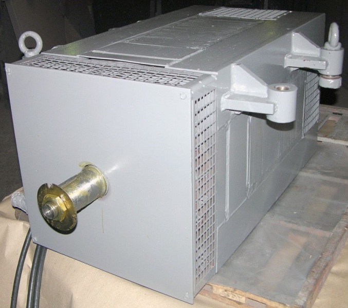
The main unit of the trolleybus is traction engine… In the classic version it is DC motor: cylindrical frame, armature with brush-collecting block, posts, end shields and fan.
Most DC trolley motors are series or compound. Motors with transistor or thyristor control only work with a series excitation system.
One way or another, trolleybus traction motors are quite impressive DC machines, designed for a power of about 150 kW and requiring an additional DC converter for normal stable operation.The motor itself can weigh about a ton and consume a current of about 300 A with an operating shaft torque of over 800 N * m (at a shaft speed of 1650 rpm).
Some of the models of modern trolleybuses carry AC asynchronous traction motors driven by dedicated AC traction converters… Engines of this type are less bulky, moreover, more powerful, they do not require regular maintenance (compared to collector engines).
But such engines need special ones semiconductor converter… The motor itself may have a pair of speed sensors that are mounted on the shaft. Most asynchronous AC traction motors are powered by 400 V, have a squirrel-cage rotor and a three-phase stator winding with a classic "star" connection.
The engine is usually located at the rear of the trolleybus body. On its drive shaft there is a flange, with the help of which a mechanical transmission is carried out through the cardan shaft to the drive axle through the drive gear.
The motor housing is completely insulated from the body, so high voltages cannot reach its conductive parts. This is ensured by the fact that the flange is made of insulating material, and the mounting of the motor on the brackets is never complete without insulating sleeves.
The modern trolleybus traction motor is driven by a transistor-pulse control system of IGBT transistors, which is considered more perfect than thyristor and even more rheostat circuits.
The system contains a switching section for connecting a diagnostic computer for the purpose of adjusting and regulating the engine control circuit, as well as for monitoring the condition of the traction equipment as a whole. Such a control system is the most economical in terms of energy consumption, and it also provides contactless starting and acceleration of the vehicle without unnecessary energy losses, as would be the case with a rheostat system.
As a result, the competent control of the traction motor provides the trolleybus smooth start, push-free speed regulation and reliable braking. An adjustable pulse voltage with an armature current of about 50 A allows the trolleybus to move smoothly, regardless of the presence of backlash in its mechanical transmissions.
Speed control is obtained steplessly also due to the possibility of weakening the field coil current when the vehicle speed reaches 25 km / h. When braking, an adjustable current is also used - this is called dynamic braking.
The rear trolley has a speed limit of no more than 25 km/h. Thanks to the electronics, stopping has priority over starting. If necessary, it is possible to change the working polarity of the pantographs.
Directly transistor-pulse trolleybus system works as follows. Pressing the foot pedal activates Hall sensor, the analog signal level from which is directly related to the current pedal position angle.
This signal is converted to digital and, already in digital form, is fed to the microprocessor controller of the traction unit, from where commands are sent to the driver's dashboard power transistors.
The drivers of the power transistors, in turn, regulate the current of the power transistors depending on the commands coming from the microprocessor controller of the traction unit. The control voltage of the drivers is a low voltage (it varies from 4 to 8 volts) and it is its value that determines the operating current of the windings of the traction motor.
You guessed it, power transistors serve here semiconductor contactorsvoltage controlled, only unlike a conventional contactor, here the current can change very, very smoothly. Hence no need for rheostats, simple enough PWM technology (pulse width modulation).
If the trolley needs to be stopped, then the engine is switched to generator mode, and the braking is essentially provided by the magnetic fields of the armature, which are also adjusted. Thus, braking is achieved almost to a complete stop of the vehicle. By the way, the main part of the control transistor-pulse electronics of the trolleybus is located on its roof.
In the process of stopping a modern trolleybus, the system works energy recovery… This means that the energy generated by the traction motor in generator mode during braking is returned to the contact network and can be reused both for the needs of electric vehicles powered in parallel from this network and for powering the devices on the trolleybus itself (hydraulic steering wheel, heating system, etc.) If the trolleybus passes under the arrow, then rheostatic braking.
Almost the entire drive of a trolleybus consists of several parts:
-
pairs of pantographs;
-
circuit breaker;
-
IGBT control unit;
-
regulatory scheme;
-
motion and brake controller;
-
block of rheostats;
-
choke to suppress interference;
-
panel computer or switching module to connect to an external computer.
With the help of a panel or an external computer, diagnostics of the traction motor of the trolleybus are carried out, the parameters of its operation are reviewed, the settings are changed if necessary microprocessor controller… All operating parameters and the current state of the traction drive are stored digitally.
Following are some models of control systems behind the leakage currents and have an appropriate protection system — automatic disconnection from the network. Optionally, it can also be present here counter of energy consumed for movement and recovered during stopping.
It is worth mentioning separately trolley protection electronics, which serves to improve passenger safety. For example, a trolleybus will not move when the passenger doors are open or there is no air in the brake system.