The time constant of an electric circuit — what it is and where it is used
Periodic processes are inherent in nature: day is followed by night, the warm season is replaced by the cold, etc. The period of these events is almost constant and therefore can be strictly determined. Moreover, we are entitled to claim that the periodic natural processes cited as an example are not depreciating, at least in terms of a person's life span.
However, in technology, in electrical engineering and electronics, especially, not all processes are periodic and continuous. Usually, some electromagnetic processes first increase and then decrease. Often matter is only limited to the phase of the beginning of the oscillation, which does not have time to really pick up speed.
Quite often in electrical engineering you can find so-called exponential transients, the essence of which is that the system simply strives to reach some equilibrium state, which eventually looks like a state of rest. Such a transition can be either increasing or decreasing.
The external force first brings the dynamic system out of equilibrium, and then does not prevent the natural return of this system to its original state. This last phase is the so-called transitional process, which is characterized by a certain duration. In addition, the process of unbalancing the system is also a transient process with a characteristic duration.
One way or another, the time constant of the transient process, we call its time characteristic, which determines the time after which a certain parameter of this process will change times «e», that is, it will increase or decrease by about 2.718 times compared to the initial state.
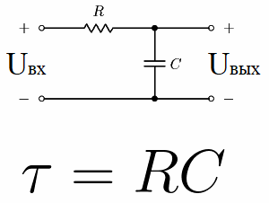
Consider, for example, an electrical circuit consisting of a DC voltage source, a capacitor, and a resistor. This type of circuit where a resistor is connected in series with a capacitor is called an RC integrating circuit.
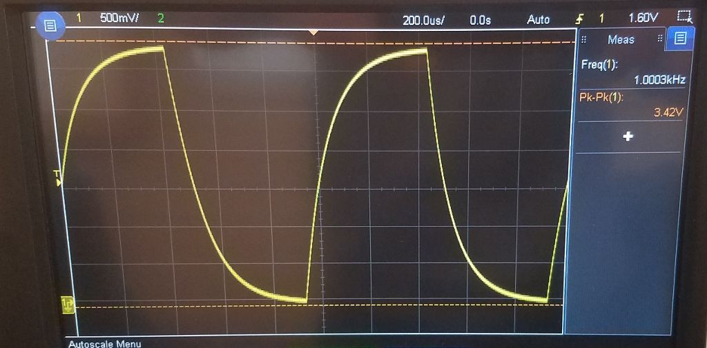
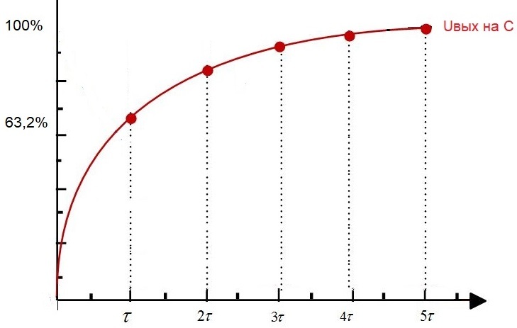
If at the initial moment of time to supply power to such a circuit, that is, to set a constant voltage Uin at the input, then Uout — the voltage in the capacitor, will begin to grow exponentially.
After time t1, the capacitor voltage will reach 63.2% of the input voltage. So, the time interval from the initial instant to t1 is the time constant of this RC circuit.
This chain constant is called «tau», measured in seconds and indicated by its corresponding Greek letter. Numerically, for an RC circuit, it is equal to R * C, where R is in ohms and C is in farads.
Integrating RC circuits are used in electronics as low-pass filters when higher frequencies must be cut off (suppressed) and lower frequencies must be passed through.
In practice, the mechanism of such filtration is based on the following principle. For alternating current, the capacitor acts as a capacitive resistance, the value of which is inversely proportional to the frequency, that is, the higher the frequency, the lower the reactance of the capacitor in ohms will be.
Therefore, if an alternating current is passed through the RC circuit, then, as on the arm of the voltage divider, a certain voltage will drop across the capacitor, proportional to its capacitance at the frequency of the current passed.
If the cut-off frequency and amplitude of the input alternating signal are known, then it will not be difficult for the designer to choose such a capacitor and resistor in the RC circuit, so that the minimum (cut-off) voltage (for the cut-off frequency — the upper limit of the frequency) falls on the capacitor, since the reactance enters the divider along with a resistor.
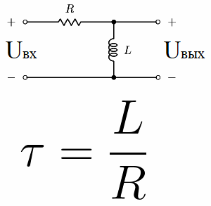
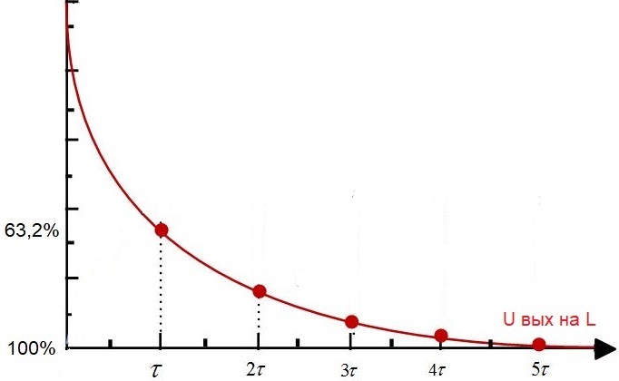
Now consider the so-called differentiating circuit. It is a circuit consisting of a resistor and an inductor connected in series, an RL circuit. Its time constant is numerically equal to L / R, where L is the inductance of the coil in henries and R is the resistance of the resistor in ohms.
If a constant voltage from a source is applied to such a circuit, after some time tau the voltage of the coil will decrease compared to U in by 63.2%, that is, in full accordance with the value of the time constant for this electric circuit.
In AC circuits (alternating signals), LR circuits are used as high-pass filters when low frequencies must be cut off (suppressed) and frequencies above (above the cut-off frequency — the lower frequency limit) — are omitted.So, the higher the inductance of the coil, the higher the frequency.
As in the case of the RC circuit discussed above, the voltage divider principle is used here. A higher frequency current passed through the RL circuit will result in a larger voltage drop across the inductance L, as with the inductive resistance that is part of the voltage divider along with the resistor. The designer's task is to choose such R and L so that the minimum (boundary) voltage of the coil is obtained exactly at the boundary frequency.