Power transformer operation for active, inductive and capacitive loads
A transformer is an electrical machine that converts alternating current of one voltage to alternating current of another voltage. The principle of operation of the transformer is based on the phenomenon of electromagnetic induction.
The first electrical power transmission networks used direct current. The voltage in the networks depends on the insulation capacity of the materials used and is usually 110 V.
With the increase in the transmission power of the networks, it became necessary to increase the cross-section of the wires in order for the voltage losses to remain within the permissible limits.
And only the invention of the transformer made it possible to economically generate electrical energy in large power plants, transmit it at high voltage over long distances, and then reduce the voltage to a safe value before delivering electricity to consumers.
Without transformers, today's power grid structures with their high and ultra-high, medium and low voltage levels would simply not be possible. Transformers are used in both single-phase and three-phase electrical networks.
The operation of a three-phase power transformer varies greatly for what load it is operating—active, inductive, or capacitive. In real conditions, the transformer load is an active-inductive load.
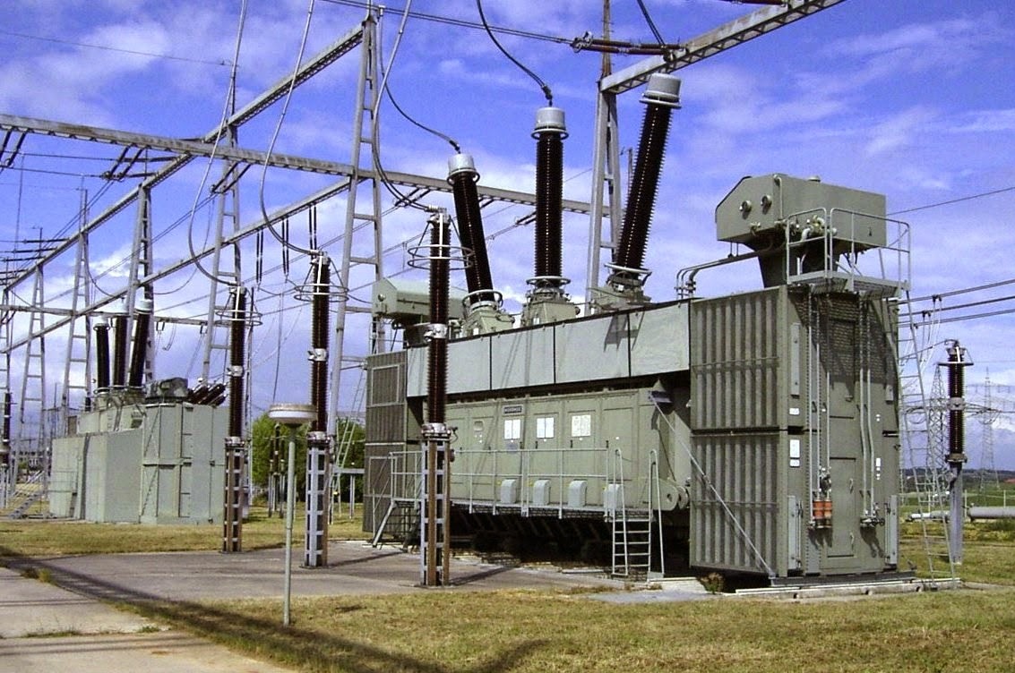
Figure 1 — Three-phase power transformer
1. Active load mode
In this mode, the primary winding voltage is close to the nominal U1 = U1nom, the primary winding current I1 is determined by the transformer load, and the secondary current is determined by the nominal current I2nom = P2 / U2nom.
According to the measurement data, the efficiency of the transformer is determined analytically:
Efficiency = P2 / P1,
where P1 is the active power of the primary winding of the transformer, P2 is the power supplied to the supply circuit by the secondary winding of the transformer.
The dependence of the efficiency of the transformer depending on the relative current of the primary winding is shown in figure 2.
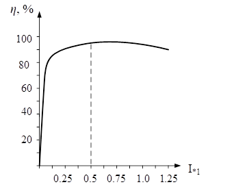
Figure 2 — Dependence of transformer efficiency on the relative current of the primary winding
In active load mode, the secondary winding current vector is co-extensive with the secondary winding voltage vector, therefore an increase in the load current causes a decrease in the voltage at the terminals of the secondary winding of the transformer.
A simplified vector diagram of the currents and voltages for this type of transformer load is shown in Figure 3.
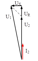
Figure 3 — Simplified vector diagram of transformer active load currents and voltages
2. Operating mode for inductive load
In inductive load mode, the secondary winding current vector lags the secondary winding voltage vector by 90 degrees. A decrease in the value of the inductance connected to the secondary winding of the transformer causes the load current to increase, resulting in a decrease in the secondary voltage.
A simplified vector diagram of the currents and voltages for this type of transformer load is shown in Figure 4.

Figure 4 — Simplified vector diagram of transformer currents and voltages in inductive load mode
3. Mode of operation with capacitive load
In capacitive load mode, the current vector of the secondary winding is ahead of the voltage vector of the secondary winding by 90 degrees. An increase in the capacitance connected to the secondary winding of the transformer causes the load current to increase, resulting in an increase in the secondary voltage.
A simplified vector diagram of the currents and voltages for this type of transformer load is shown in Figure 5.
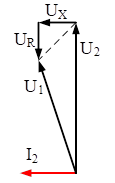
Figure 5 — Simplified Vector Diagram of Transformer Capacitive Load Mode Currents and Voltages