Thermal relays — device, principle of operation, technical characteristics
Thermal relays are electrical devices designed to protect electric motors from overcurrent. The most common types of thermal relays are TRP, TRN, RTL and RTT.
The principle of operation of thermal relays
The durability of power equipment depends to a large extent on the overloads it is subjected to during operation. For each object, it is possible to find the dependence of the duration of the current flow on its magnitude, where reliable and long-term equipment operation… This dependence is shown in the figure (curve 1).
At nominal current, the permissible duration of its flow is infinity. A current flow higher than the nominal leads to an additional increase in temperature and additional aging of the insulation. Therefore, the greater the overload, the shorter the time allowed. Curve 1 in the figure is set based on the required life of the equipment. The shorter its life, the greater overloads are permissible.
Time current characteristics of the thermal relay and the protected object
With ideal object protection, the tav (I) dependence for the thermal relay should go slightly below the object curve.
For overload protection, thermal relays with bimetallic plate.
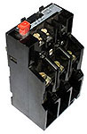 The bimetallic plate of the thermorelay consists of two plates, one of which has a higher temperature coefficient of expansion, the other has a smaller one. At the place of adhesion to each other, the plates are rigidly fixed either by hot rolling or by welding. If such a plate is fixed stationary and heated, then the plate will bend to the material less. This phenomenon is used in thermal relays.
Invar (small value) and non-magnetic or chromium-nickel steel (large value) materials are widely used in thermal relays.
The bimetallic element of the thermal relay can be heated by the heat generated in the plate by the load current. Very often, the bimetal is heated by a special heater through which the load current flows. The best characteristics are obtained with combined heating, when the plate is heated both due to the heat generated by the current passing through the bimetal and due to the heat generated by a special heater, also by the streamlined load current.
Bending, the bimetallic plate with its free end acts on the contact system of the thermal relay.
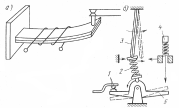
Thermal relay device: a — sensitive element, b — jumper contact, 1 — contacts, 2 — spring, 3 — bimetallic plate, 4 — button, 5 — bridge
Current-time characteristics of the thermal relay
The main characteristic of the thermal relay is the dependence of the response time on the load current (current-time characteristic).In the general case, before the overload starts, a current Io flows through the relay, which heats the plate to a temperature qo.
When checking the current-time characteristics of thermal relays, it must be taken into account from which state (cold or overheated) the relay is triggered.
When checking thermal relays, it should be taken into account that the heating elements of thermal relays are thermally unstable at short-circuit currents.
Thermal relay selection
The rated current of the thermal relay is selected based on the rated load of the motor. The selected thermal relay current is (1.2 — 1.3) of the rated motor current (load current), that is, the thermal relay is activated at 20 — 30% overload for 20 minutes.
The heating constant of the electric motor depends on the duration of the current overload. In the event of a short-term overload, only the motor winding participates in heating and a heating constant of 5 — 10 minutes. In case of prolonged overload, the entire mass of the electric motor participates in the heating, and the heating is constant for 40-60 minutes. Therefore, the use of thermal relays is only recommended when the switch-on time is more than 30 minutes.
Effect of ambient temperature on thermal relay operation
 The heating of the bimetallic plate of the thermal relay depends on the ambient temperature, therefore, as the ambient temperature increases, the operating current of the relay decreases.
At a temperature that is very different from the nominal one, it is necessary either to carry out additional (smooth) regulation of the thermal relay, or to select a heating element, taking into account the real ambient temperature.
In order for the ambient temperature to have less influence on the tripping current of the thermal relay, it is necessary to select the tripping temperature as high as possible.
For the correct functioning of the thermal protection, it is recommended to place the relay in the same room as the protected object. The relay should not be located near concentrated sources of heat — heating furnaces, heating systems, etc. Temperature compensated relays (TPH series) are currently being manufactured.
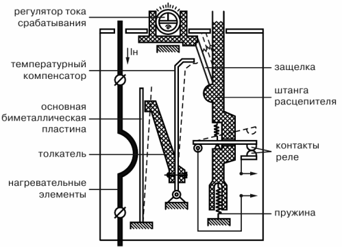
Thermal relay design
The deflection of the bimetallic plate is slow. If the movable contact is directly connected to the plate, then the low speed of its movement will not be able to extinguish the arc that occurs when the circuit is turned off. Therefore, the plate acts on the contact through an accelerating device. The most perfect is the «jumping» contact.
In the off state, the spring 1 creates a torque relative to point 0, which closes the contacts 2. The bimetallic plate 3 bends to the right when heated, the position of the spring changes. It creates a moment that opens 2 contacts at once, providing reliable arc extinguishing. Modern contactors and starters are equipped with TRP (single-phase) and TRN (two-phase) thermal relays.
Thermal relays TRP
 Single-pole thermal current relays of the TRP series with nominal currents of thermal elements from 1 to 600 A are mainly intended for protection against unacceptable overloads of three-phase asynchronous electric motors operating from a network with a nominal voltage of up to 500 V at a frequency of 50 and 60 Hz. TRP thermal relays for currents up to 150 A are used in DC networks with a nominal voltage of up to 440 V.
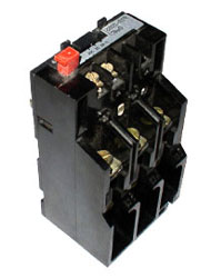
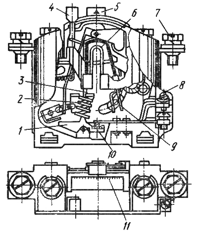
Thermal relay device type TRP
The bimetallic plate of the TRP thermorelay has a combined heating system. The plate is heated both by the heater and by the passage of current through the plate itself. When deflected, the end of the bimetallic plate acts on the jumper contact bridge.
The TRP thermal relay allows smooth adjustment of the operating current within (± 25% of the nominal setting current). This adjustment is done with a knob that changes the initial deformation of the plate. This setup can dramatically reduce the number of heater options required.
The return of the TRP relay to its initial position after operation is carried out by the button. It is also possible to perform self-recovery after the bimetal has cooled.
The high reaction temperature (over 200 ° C) reduces the dependence of the relay operation on the ambient temperature.
The setting of the thermal relay TRP changes by 5% when the ambient temperature changes to KUS.
The high impact and vibration resistance of the TRP thermorelay allows it to be used in the most difficult conditions.
Thermal relays RTL
 The RTL thermal relay is designed to protect electric motors from current overloads of unacceptable duration. They also provide protection against asymmetry of currents in phases and against failure of one of the phases. RTL electric thermal relays with a current range of 0.1 to 86 A.
RTL thermal relays can be installed both directly on PML starters and separately from starters (in the latter case, they must be equipped with KRL terminal blocks). RTL relays and KRL terminal blocks have been developed and manufactured which have a degree of protection IP20 and can be installed on a standard busbar.The rated current of the contacts is 10 A.
PTT thermal relay
RTT fuel relays are designed to protect three-phase squirrel-cage induction motors from overloads of unacceptable duration, including those resulting from the loss of one of the phases, as well as from phase asymmetry.
PTT relays are intended for use as components in electric drive control circuits as well as for installation in magnetic starters PMA series for 660V alternating current with a frequency of 50 or 60 Hz, for 440V direct current purposes.