Fuse calibration
Pre-selection of fuse wire
 A blown fuse, if not factory made, can be replaced with a calibrated copper wire. When calibrating a copper wire for fuses, the following GOST requirements should be considered:
1. At current Imax = (1.62 … 2.1) Ipl.wst. the fuse must burn in 1 ... 2 hours,
2. At current Imin = (1.25 … 1.5) Ipl.wst. the fuse must not burn.
In advance, the diameter of the copper wire can be determined by the formula:
where d is the diameter of the wire, mm; Ipl.vst — fuse current, A.
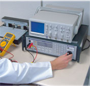
Test bench for circuit breakers and fuses
The schematic diagram of the circuit breaker and fuse test stand is shown in the figure.
The stand is powered by 220 V AC (input X1). Fuses F1 and F2 are provided to protect the power supply and auxiliary circuits against short circuits. The power supply and auxiliary circuits are switched on using the magnetic starter KM. When the «Start» button of the magnetic starter is pressed, the voltage of 220 V is applied to autotransformer AT in the supply circuit, transformer T2 in the signal circuit, as well as on the electric stopwatch RT.
The autotransformer AT serves to regulate the current and voltage supplied to the primary winding of the transformer T1.
Schematic diagram for automatic testing of switches and fuses
Main functions of the transformer T1:
1. galvanic isolation of input and output circuits, which is dictated by safety requirements;
2. lowering the output voltage (to units of volts) and making it possible to have significant currents in the secondary circuit of the transformer (at the X2 output) (up to 100 A; for this, the secondary winding of the transformer T1 is wound with a wire of large cross-section) .
Transformer TA is included in the secondary winding of transformer T1. The ammeter RA is connected in series to the secondary winding of the current transformer TA, which is necessary for monitoring the current and the current relay KA, which with its contacts AKV-KA in the circuit of the electric stopwatch RT turns off the latter when the current in the supply circuit disappears.
The switch QV (switch) in the electric chronometer serves to turn off the latter when necessary.
Transformer T2 is used to obtain the necessary voltage to supply the signal circuit. The signal circuit includes signal lamps HL1 and HL2, which are turned on by the corresponding contacts of the magnetic starter AKV-KM and signal that the starter is turned on; signal lamps HL3, HL4, HL5 signal the activation of the respective machine.
The rack contains three circuit breakers of different types QF1, QF2, QF3 and three fuses of different types F1, F2, F3, which are connected to the supply circuit for the appropriate test by separate wires.
Calibrating fuses and ensuring selectivity of their operation
Calibration of copper wire fuses can be done on the bench as described above. For this, wire with different diameters is obtained. If the diameter of the wire is unknown, it can be determined with a micrometer.
Approximately for a given diameter, the rated current of the fuse can be determined by the formula:
where d is the diameter of the wire, mm.
To do this, part of the time is removed on the stand — the current characteristic tсgr = f (I), i.e. the dependence of the burning time of the wire on the value of the current I is obtained.
The values of the currents are taken when taking the specified characteristic:
where K is the multiplicity factor.
It is usually sufficient to remove part of the feature at K = 1.5; 2.0; 3.0; 4.0.
The experiment is carried out in the following order:
 1. Load the fuse holder with wire. It is impossible to install the wire without a cartridge due to the possible spread of metal and non-compliance with the operating conditions of the future fuse.
2. The loaded cartridge is placed on the rack in the corresponding jaws and connected to terminals X2.
3. Turn off the PT electric stopwatch with the QV switch and set it to the zero position.
4. Install a jumper on the X2 terminals, bypassing the fuse.
5. The autotransformer is set to the zero position.
6. Turn on magnetic switchby clicking the Start button.
7.By turning the AT autotransformer knob, set the required current value, which is monitored using an RA ammeter.
8. After setting the required current value, use the "Stop" button to turn off the KM magnetic starter. Remove the jumper from the X2 terminals and turn on the electric timer with the QV switch.
9. Turn off the magnetic starter. At the same time, the electric chronometer RT starts working. The magnitude of the current is monitored using an RA ammeter.
10. After burning the wire, the electric stopwatch will turn off automatically. The «Stop» button turns off the magnetic starter. The value of the current and the readings of the electric stopwatch are recorded in the logbook.
Experiments are then carried out for other current values. The dependence tsgr = f (I) was constructed.
Using the resulting dependence tcor = f (I) for time t = 10 s, I10 is found.
The rated current of the fuse will be determined by:
It is often necessary to choose the diameter of the copper wire for a fuse with a given value of the rated current of the fuse, i.e. you need to solve the opposite problem described above. For this, the diameter of the copper wire is determined approximately by the formula:
Find a copper wire of the required diameter and test it on a stand at a current of I = 2.5In..pl.vst.
If the burning time of the wire turns out to be more than 10 s, choose a wire one step smaller in diameter and repeat the experiment until the diameter of the wire at which it burns in 10 s is found.
The fuses are checked for selectivity of operation by connecting the fuses in series to terminals X2.At the same time, a current is set that exceeds the rated current of the fuse of the smaller of the fuses by 2.5 times, and make sure that only its fuse burns for a time not exceeding 10 s.