Repair of transformers for powering control and signal circuits
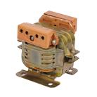
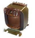
Transformers for powering control and signal circuits consist of a core assembled from thin metal lacquered plates (usually W-shaped) and a frame with enamelled copper wire windings. To reduce losses due to hysteresis, the plates are made of a special t. Name Transformer steel or permaloid alloy.
Transformers, especially power transformers, carry a constant electrical and thermal load. If the calculation and production of transformers are carried out with deviations, for example, the soldering of wires is carried out with acid fluxes, then the reliability of the manufactured transformers decreases and they, more often than other winding products, fail to work.
The most typical malfunctions of transformers for powering control and signal circuits the following: violation of soldering at the points of connection of the ends of the output wires, internal breaks in the windings, short-circuiting of the windings to each other and to the housing.
The procedure for repairing transformers for control circuits
Prepare winding wires, flexible wiring for cables, cushioning cable paper or thin fluoroplastic insulating film, cambric, threads, shellac varnish, soldering iron, solder, acid-free flux, finely shredded paper or cloth.
To determine the nature of the malfunction of the transformer for the control and signaling circuits, the wires connected to it are soldered and all the wires that will be soldered are marked with labels so that the connection is not confused in the future.
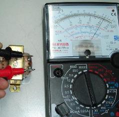
 Troubleshooting the transformer produced by external inspection and inspection in the following order: with an ohmmeter check the integrity and resistance of the windings, a megohmmeter is used to check the insulation resistance between the windings and between the case (core) and the windings, with an AC voltmeter check the voltage of the terminals of the secondary windings at the rated voltage of the primary winding, An AC milliammeter is used to check the no-load current of the transformer.
When a malfunction is detected, the transformer is disassembled, that is, the fasteners are removed and the core plates are removed. This is done carefully, as bent plates will further complicate the assembly of the core. Permaloid plates should not be subjected to shocks, bends and other deformations that deteriorate the magnetic conductive properties of permaloid plates, which can affect the operation of electronic devices, in particular potentiometers.
Rewinding windings of control and signal chain transformers
If there is no information about the winding data, then the windings to be removed are unwound on a winding machine with a counter to establish the number of turns. The diameter of the wire is determined with a micrometer. If winding data is present, the wire can be cut without damaging the working windings and frame.
 If during operation the transformer heats up above the permissible nominal temperature, you must make sure that the insulation of the windings left without rewinding is sound: the paper seals between the layers do not contain burnt spots (they do not darken), the enamel coating on the winding wire is strong fastened.
In low-power transformers, the connections of the ends of the windings to the output wires during winding are insulated with a thin fluoroplastic film, and each coil, after wrapping it with a film and gluing the film, is tied with a thread that simultaneously fixes the output wires. The coil turns out to be quite rigid, and in addition, the impregnation makes the winding of the coil even more rigid. Therefore, especially with thin wires, it is difficult to unwind the coil to count the number of turns, and care must be taken not to break the wire during winding.
The winding is conducted cycle to loop. In this case, the windings will take up significantly less space than with random winding, and there will be a minimal possibility of destruction between turns. After completing the row from right to left, they wind the next row in the opposite direction. After each row (layer) of wires, a paper gasket or fluoroplastic film is laid, which must fit tightly in width between the cheeks of the frame.Do not allow the wire to get between the seal and the frame cheek. The thickness of the coil turns out to be slightly larger where the leads are located, so they must be placed on the side of the coil, which after assembling the core will not be placed inside the core, but outside it. The electrical wires pass through the holes in the frame cheeks.
 The enameled wire used for winding must be covered with a continuous uniform layer of enamel film, the surface of which must be smooth, shiny, without bubbles, foreign bodies, without mechanical damage to the upper layers of the metal. Take a wire of the same diameter and keep the same number of turns, otherwise it will not fit in the frame.
After winding all the windings, the transformer coil is taped on top with new tape or tape removed from the transformer before unwinding to protect against mechanical damage and dust.
Assembly of transformers after repair
Before assembling the core, check the condition of the plates, straighten the bent ones. If there are traces of rust on the iron plates, they are cleaned of rust and covered with a thin layer of bakelite varnish. When assembling, the middle branch of the W-shaped plate is inserted into the coil frame, the outer ones are left outside the coil. The assembly is carried out so that the plates are installed in sequence, then on one side or the other of the coil, which is necessary to create a closed magnetic flux in the core.
When assembling the core, be careful not to crush the plates and at the same time not to damage the coil frame.Plates made of transformer iron are more rigid and rarely crush when the core is packed. Permalloy plates are thinner, which is why they often wrinkle, bend, which complicates assembly. The last two or three plates are put in place with light blows of a wooden hammer. After that, the core is pressed in a vise, and additionally with the help of blows from a wooden hammer, two or three more plates are installed. If the plates are not tightly packed, then when switched on the transformer hums.
At the end of the core assembly, the set bolts are inserted and the core is pulled together.
In order to increase the moisture resistance, heat resistance, electrical and mechanical strength of the transformer windings, the windings are impregnated with an insulating melamine-glyphthal varnish.
At the end of drying, an electrical supply is connected to the transformer and its winding voltage, winding integrity, insulation resistance and no-load current are checked.
They also check if the transformer hums loudly, which can be the result not only of weak core punching, but also of insufficient tightening of the core.