How to measure active power in a single-phase AC circuit
Value of active power in single phase alternating current circuit is determined by the formula P = UI cos phi, where U is the receiver voltage, V, I — receiver current, A, phi — phase shift between voltage and current.
From the formula, it can be seen that the power in an alternating current circuit can be determined indirectly if you include three devices: an ammeter, a voltmeter and phase meter… In this case, however, greater accuracy of measurement cannot be relied upon, since the power measurement error will depend not only on the sum of the errors of the three devices, but also on the error of the measurement method caused by the way, on which ammeter and voltmeter are included. Therefore, this method can only be used when high measurement accuracy is not required.
If active power needs to be measured accurately, then it is best to use electrodynamic system wattmeters or electronic wattmeters. Ferrodynamic wattmeters can be used for rough measurements.
If the circuit voltage is less than the voltage measurement limit of the wattmeter, the load current is less than the allowable current of the measuring device, then the circuit for connecting the wattmeter to the AC circuit is similar diagram for connecting a wattmeter to a DC circuit… This means that the current coil is connected in series with the load and the voltage coil is connected in parallel with the load.
When connecting electrodynamic wattmeters, it should be borne in mind that they are polar not only in the DC circuit, but also in the AC circuit. To ensure the correct (to scale) deviation of the instrument needle from zero, the start of the windings on the instrument panel is indicated by a dot or an asterisk. Clamps marked this way are called generator clamps because they are connected to a power source.
The fixed coil of the wattmeter can be connected in series with the load only at load currents of 10 — 20 A. If the load current is greater, then the current coil of the wattmeter is connected through a measuring current transformer.
To measure power in an AC circuit with a low power factor, special low-cosine wattmeters must be used. Their scale indicates which values of cos phi they are intended for.
When cos phi <1, then to avoid overloading the electrodynamic wattmeter, you should include the control ammeter and voltmeter. For example, a wattmeter with a rated current of Azu = 5 A can show a full current deviation of Azu = 5 A and cos phi = 1 and at a current of Azu = 6.25 A and cos phi = 1 (so Azu = Azun / cos phi). In the second case, the wattmeter will be overloaded.
The inclusion of a wattmeter in the AC circuit, with a load current greater than the permissible one
If the load current is greater than the permissible current of the wattmeter, then the current coil of the wattmeter is switched on by means of a measuring current transformer (Fig. 1, a).
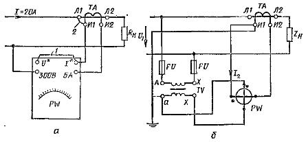
Rice. 1. Schemes for connecting a wattmeter to a high-current alternating current circuit (a) and to a high-voltage network (b).
When choosing a current transformer, it must be ensured that the nominal primary current of the transformer is Az1 and is equal to or greater than the measured current in the network.
For example, if the value of the current in the load reaches 20 A, then you can take a current transformer designed for a primary rated current of 20 A with a rated current transformation factor Kh1 = Az1i/ Az2i = 20/5 = 4.
If in this case the voltage in the measuring circuit is less than the permissible wattmeter, then the voltage coil is connected directly to the load voltage. The start of the voltage coil is jumpered / to the start of the current coil. It is also necessary to install jumper 2 (the beginning of the coil is connected to the network). The end of the voltage coil is connected to another terminal of the network.
To determine the actual power in the measured circuit, the wattmeter readings must be multiplied by the nominal transformation ratio of the current transformer: P = Pw NS Kn1 = Pw NS 4
If the current in the network can exceed 20 A, then a current transformer with a primary rated current of 50 A must be selected, while Kn1 = 50/5 = 10.
In this case, to determine the power value, the wattmeter readings must be multiplied by 10.