Wire Continuity Methods and Box Circuit Diagrams
 Finding suitable strands of wires and cables to connect them together and to connect to the terminals of devices and devices is called continuity. This operation is carried out after the completion of laying wires and cables, installation of switches, lamps and sockets, as well as during the operation of electrical equipment when searching for wiring faults.
To familiarize yourself with the methods and procedure for making a continuous call, let's turn to the electrical diagram of the apartment (Fig. 1). The phase and neutral wires from the supply line are introduced into box B, from which two wires are laid for connecting socket 5 and five wires in the ceiling duct (three for chandelier 4 and two for connecting devices in a small room). In addition, three more wires from the glow switch 6 were fed into box B.
A total of twelve wires are connected to box B. Eight wires are fed into box A—phase and neutral from the box, and two wires each for the lamp, switch, and plug.For simplicity, we will depict this diagram so that all sections of the wiring are represented more clearly (Fig. 2).
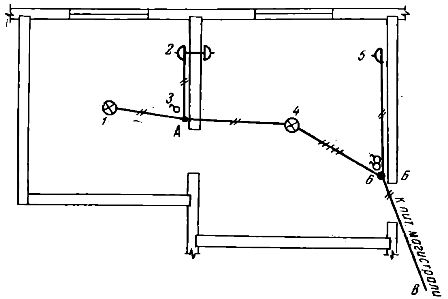
Rice. 1. Section of apartment wiring
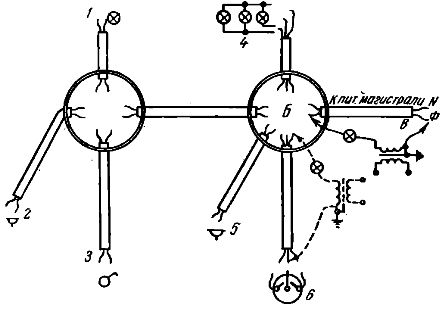
Rice. 2. Continuity diagram of wires in boxes
To correctly connect the wires in box B, you need to determine which of the wires in the B — B section will serve as phase and which will be neutral. Next, you need to ring the wires in sections B-6 and B-4. It is not necessary to call section B-5, since for the operation of the output it is completely indifferent which of its contacts will be phase and which will be zero.
The same applies to the B-A section: in box B, these wires can be randomly connected to phase or neutral, and then when box A rings, the phase and neutral wires can be determined. Calling box L, you only need to find the neutral wire (to connect it to the threaded contact of the cassette) in section A-1 (sections A-2 and A-3 should not ring).
Often, the continuity of the wires is carried out using a 12 or 42 V lamp (depending on the degree of danger of the room). To obtain such a voltage, a step-down transformer Tr (Fig. 3) is used, which is connected to a 220 V network. Dialing using a transformer and a lamp is based on finding a closed circuit in which the lamp lights up. This operation can be started from any box after making sure that there is no voltage in all sections of the circuit and the lamps are disconnected from the sockets (if the lamps are connected).
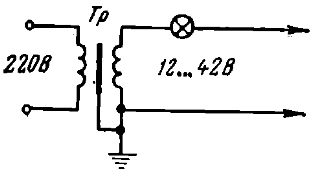
Fig. 3. Connection diagram of a step-down transformer for wire continuity
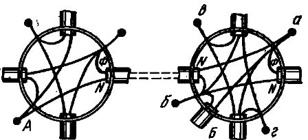
Rice. 4. Wiring diagram in boxes
For continuity and connection of wires in box B, which has a more complex circuit, they first determine which of the two wires, suitable from the supply line, is phase. To do this, one terminal of the transformer is connected to point F, and the other terminal successively touches the wires introduced into the box.
The wire, when touched, the lamp lights up and will be phase. Now you can connect to it a wire going to output and one of the wires going to box A. (Dial tone is also detected.)
The neutral wire coming from the main line is also looked for in box B in the same way as phase one, and the second wire of the socket is connected to it, the second wire goes to box A and the neutral wire of the chandelier (found by dialing). All neutral wires are connected to node b. The idle wires coming from the glow switch are then connected to the wires feeding both sets of chandelier lamps (nodes c and d). In the same way, ring and connect the wires in box A.