Height of overhead power line supports
 The height of the supports depends on the sagging of the wire, the distance from the wire to the ground, the type of support, etc. The height of the support with a horizontal arrangement of the wires on lines without protective cables (Fig. is determined by the following values:
1. The required distance hg of the conductor from the ground (the extent of the proximity of the conductor to the ground).
The conductors of "overhead lines must be suspended at such a height that there is a distance from their lowest points to the surface of the earth which ensures the safety of traffic." Not only people can pass under the wires, but also cars loaded with bulky objects, tall agricultural machines, cranes, etc. An electric discharge from the line conductor must not occur on them.
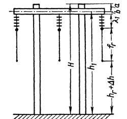
Rice. 1. Support height
The smallest permissible distances from wires to the ground and some engineering structures are given in a table. 1.
Table 1. Dimensions of the convergence of wires to the ground and engineering structures
Characteristics of terrain and intersections Line voltages, kV below 1 kV 1 — 20 35 — 110 220 Uninhabited area, often visited by people and accessible to transport and agricultural machinery. Distance to the ground, m 5 6 6 7 Populated areas and territories of industrial enterprises. Distances to the ground, m 6 7 7 8 At the intersection of permanent railways. Distance to the head of the rail, m 7.5 7.5 7.5 8.5 At the intersections of highway roads. Distance to the roadway, m 6 7 7 8
The given distances must be maintained under normal operating conditions of the lines. In some cases, for lines with suspended insulators, it is necessary to check the distances obtained when one of the wires is broken.
2. Distance in the head of distance from wire to ground Δh.
When tracing overhead lines, cross profiles are removed only in uneven terrain. The longitudinal profiles of the route of the lines along which the design placement of the supports is carried out are drawn on a vertical scale of 1: 200 — 1: 500. Inaccuracies in the survey and drawings can lead to the distances of the wires above the ground during the construction of lines, which are less than prescribed «Rules for the construction of electrical installations».
To avoid confusion, the height of the support is determined with a small margin. Δh, taken as 0.2 — 0.4 m. The smaller figure is taken for distances of up to 200 — 250 m, and the larger figure for distances of 400 — 500 m. For distances of 200 m and more - a bit with a calm profile stock terrain Δh can be omitted.
3. Overall sag of the wire is d, where the distance from the wire to the ground or engineering structure is the smallest.
The total sag of the wire when determining the height of the support can be when:
1) the highest ambient temperature and the load of the wire only from its own weight, without wind;
2) ice, temperature θd, no wind.
Most of these arrows are sags of the wire and are taken when determining the height of the support.
When checking the proximity of the conductor to the ground and engineering structures in the emergency mode of operation of the line, a break in the conductor is assumed in the section that gives the greatest sagging of the conductor in the control section. For example, when crossing a communication line with an overhead line with intermediate supports, the break is assumed to have occurred in the section adjacent to the crossing.
In emergency operation modes of power lines, the permissible distances from the wires to the ground and some engineering structures are set smaller than in normal operation modes of the lines.
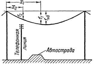
When the crossed object — highway, communication line, etc. — is not in the middle of the section (fig. 2), but is located closer to one of the supports, when determining (the height of the support should be taken into account not only the largest sagging of the wire enb, but also sagging arrows f1 and f2 over intersected objects.
The suspended boom of the conductor at a distance x from the point of its suspension is found by the formula f = γNS (l-NS)/2
Rice. 2… Support height with triangular arrangement of wires.
4. The length of the insulator string λ1, including the fittings required to attach the insulator string to the pole. To determine λ1, the lengths of the garlands given in the table should be used. 1, add 100mm for wooden supports and ~150mm for metal and reinforced concrete.
5.Size b — the distance from the lower edge of the traverse to its axis, depending on the structure of the support.
6. Dimension a — the distance from the axis of the traverse to the top of the support, determined by the supporting structure.
Therefore, the height of the support relative to the axis of the traverse is determined as equal to: h1 = hr + Δh + er + λ1 + b
Full height of the support H = h1+ a.
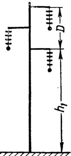
Rice. 3. Support height with triangular arrangement of wires
When placing wires, for example, in the vertices of a triangle (Fig. 3) height h1 the axis of the lower course above the ground is determined in the same way as indicated above. The position of the upper stroke is by increasing h1 distance D, (taken between conductors of different phases.
The presence of safety cables increases the height of the supports. The required distance from the top wire to the cable is added.