Determination of compliance of the output ends of the stator windings of three-phase current machines
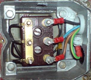
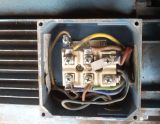 The most common arrangement of terminals in the motor terminal box is shown in fig. 1. Clips C1 — C4, C2 — C5 and C3 — C6 denote the beginning and ends of the winding of the 1st, 2nd and 3rd phases, respectively.
In fig. 1, a shows the installation of jumpers and connection to the network when connecting the windings in a star, and in fig. 1, b — when connected by a triangle.
There are cases when the individual ends of the stator phase windings are incorrectly connected to the terminals, or when the paint rubs off on the output ends of electric motors that do not have a terminal box. If the ends of the wires are not connected correctly, the motor hums abnormally and cannot run at full load. It is not recommended to establish the correct connection of the motor windings with test connections to the mains.
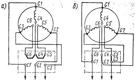
Rice. 1. Arrangement of clamps and jumpers in the terminal box of the induction motor
First of all, it is necessary to determine which wires belong to the winding of each phase.This can easily be done with a megohmmeter or test lamp (Fig. 2, a). One probe of the test lamp is connected to the lighting network and the other to one of the winding terminals connected at the other end to the same network; by feeding the other terminals with a probe in series from the network, they find the terminal that lights the N lamp.
Having found in pairs the conclusions of the windings of each of the three phases, they begin to determine the terminals of the same name conditionally - the beginning or the end). To do this, any two phase windings are connected in series and connected to the mains voltage, and a PV voltmeter is connected to the phase terminals (Fig. 2, b).
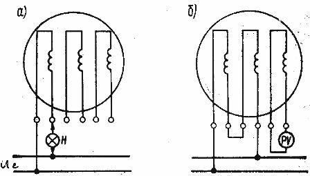
Rice. 2. Determination of the compliance of the output ends of the windings of three-phase machines
If the voltmeter shows the voltage at the terminals of the coils of both phases, they are connected in series with opposite ends (end to start). If the voltmeter reading is close to zero, it means that the phase windings are connected in series with the same ends (starting with the beginning or ending with the end).
Instead of a voltmeter, you can use a lamp designed for the applied voltage. If the glow is full, the windings of the two phases are connected to opposite terminals; if there is no light, the phase windings are connected to the same terminals.
The ends of the windings of two series-connected phases are then marked accordingly (for example, AzH, AzDA SE, IIH, IIDA SE). It does not matter which conclusion is conditionally considered the beginning or the end, it is only important to observe the polarity of the windings of one phase relative to the other.After that, the series-connected windings of the phases are turned off, one of them is connected in series with the winding of the third phase, and a voltmeter is turned on.
The location of the clamps and jumpers in the terminal box of the asynchronous motor to the remaining phase winding, the ends of the same name are determined by the method given above. The terminals of the winding of the third phase are marked in accordance with the already made marking of the conclusions of the winding of the other phase connected in series with it.
Therefore, these two methods are quite enough to determine the conclusions, after which it is easy to turn on the stator winding in a star or delta (see Fig. 1). It should be noted that C1 corresponds to IH, C2 — IINS3 — IIIH, C4 — IK, C5 — IIK, C6 — IIIDA SE.