Insulation of power lines
 For a long time, energy experts have developed a tradition of calling devices for transmitting electricity from a source (generator) to a consumer with the term "line", although they have a very complex technical design and in some cases extend to several hundreds or thousands of kilometers.
Simply put, each transmission line consists of only two components:
-
current lead systems that ensure the flow of electric currents;
-
the dielectric medium surrounding these wires to prevent electricity from passing in an unnecessary direction. This environment is simply called isolation.
According to the method of insulation materials used, power lines are divided into:
-
air;
-
cable.
Overhead power lines
These structures use the dielectric properties of the air of the surrounding atmosphere to insulate current conductors. This takes into account the fact that his resistance varies depending on weather, temperature, humidity and other parameters. To eliminate these factors, the optimal distance between the wires is selected for each type of voltage.As its value increases, the safe distance of the wires from each other increases.
Since the potential of any current conductor can flow to ground, the phase conductors also move away from the ground surface. In practice, however, they rise much higher, as people can walk or work under them, transport vehicles move and outbuildings can be located. All this is taken into account by the design of the support on which the wires are fixed.
Insulation of overhead power lines
In addition to choosing the air distance between the wires and the ground, it is necessary to fix the current wires on the masts so as not to disturb their electrical resistance. After all, the materials used for supports (wood and concrete in wet weather and metal structures in all circumstances) are good conductors of electricity.
To fix open wires on the masts of the supports, special structures are used, which are called insulators... They are made of a resistant dielectric material. Most often they choose special types of porcelain, glass or, less often, plastics.
The design of a separate type of porcelain insulators is shown in the photo.
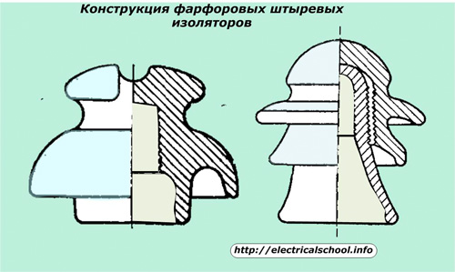
The insulator shown at left is made from a single piece of porcelain. And the right consists of two parts.
According to the method of attachment to the mast, insulators are divided into:
-
pin structures that are attached to a metal pin mounted on the traverse in a vertical position;
-
suspended devices suspended from a mast;
-
tension patterns fixed in a horizontal plane to resist tensile forces.
All of them are manufactured to work at a certain class of mains voltage. At the same time, they perceive significant mechanical forces in the vertical and horizontal direction created by the wires attached to them in all weather conditions.
Strong gusts of wind, even in combination with accumulation of snow and ice, should not impair the mechanical strength of insulators and wires, and prolonged rain and even rain should not impair their electrical resistance. Otherwise, there will be an emergency mode, the removal of which will require huge costs.
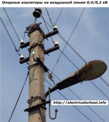
The photo below shows an example of fixing open wires of a single-phase 220-volt line on the traverse of a support mast when connecting a street lighting device using porcelain insulators.
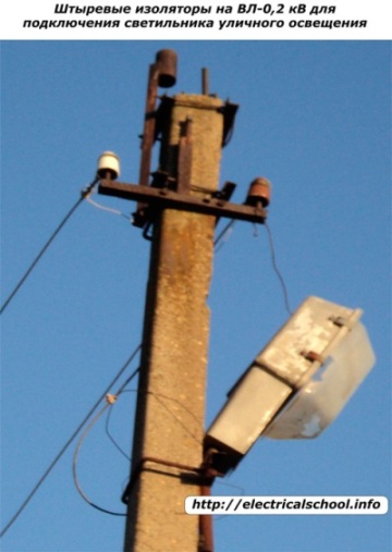
This method is widely used to illuminate roads, sidewalks, areas of the territory. The material of such an insulator can withstand mechanical forces of:
-
tensioning of wires acting in the horizontal plane along the axis of the power line;
-
the weights of the structure suspended on them acting on the compression of the isolator.
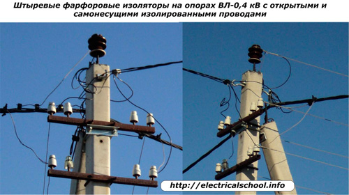
The same designs are used for 0.4 kV lines.
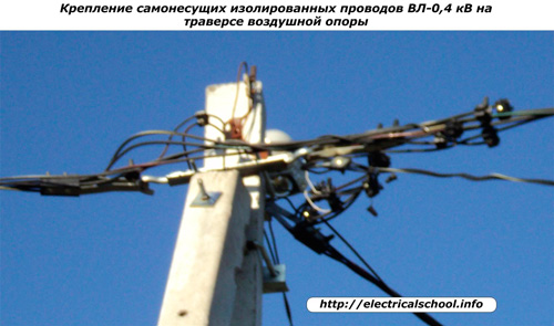
Open metal conductors are replaced by overhead power lines with voltage up to and including 35 kV. self-supporting insulated structures.
When using them, porcelain or glass insulators are not used, but the cable and wire fastening system shown in the photo.
On poles where exposed wires and self-supporting structures are connected, both types of fastening are used.
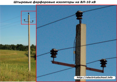
As the voltage applied to the overhead transmission line increases, the sizes of the insulators and their dielectric properties increase.More powerful insulators work on 10 kV overhead lines.
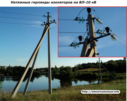
To absorb the horizontal tension forces of the wires in places where the lines turn, for example, to bypass tanks, tension insulators are used, which can consist of garlands.
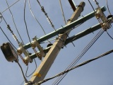
The photo shows the combined use of support and tension insulators on a reinforced support support of VL-10 kV.
The same structures are installed on supports with disconnectors… Support insulators ensure the operation of movable blades and fixed fixed contacts of the disconnector, and voltage insulators absorb the pulling forces of the conductors.
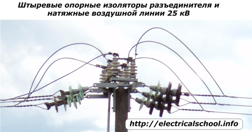
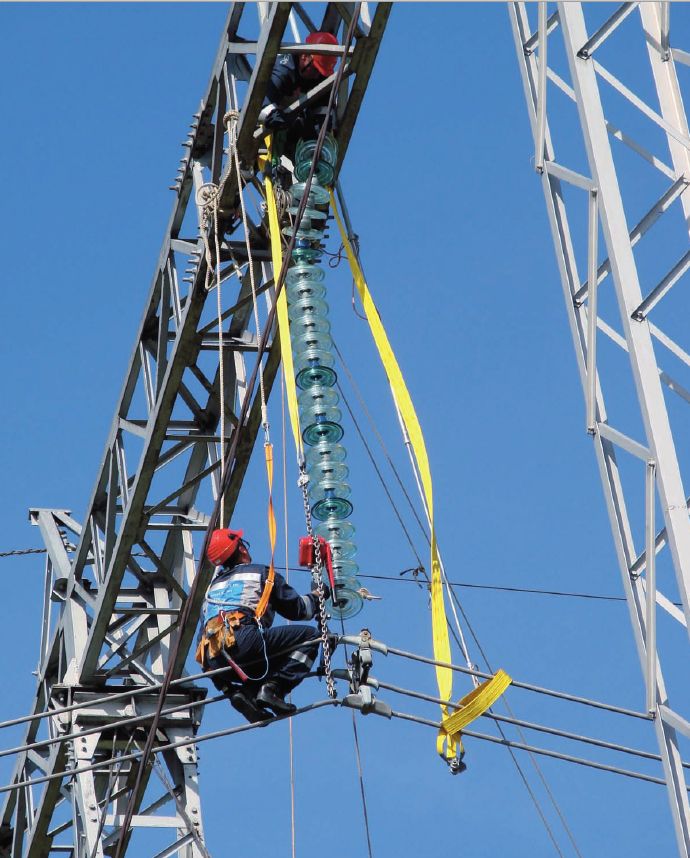
The photo confirms that the design of all 25 kV overhead line insulators has become more complex. They increased the distance between the current conductors of the power line and the carrier material.
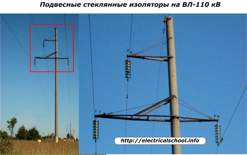
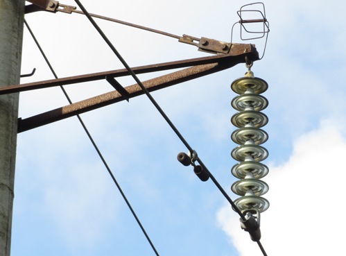
This is clearly visible on the 110 kV overhead line, where the string of insulators has become longer and their suspended construction is now used.
The ends of the overhead lines are connected to transformer bushings located at substations.
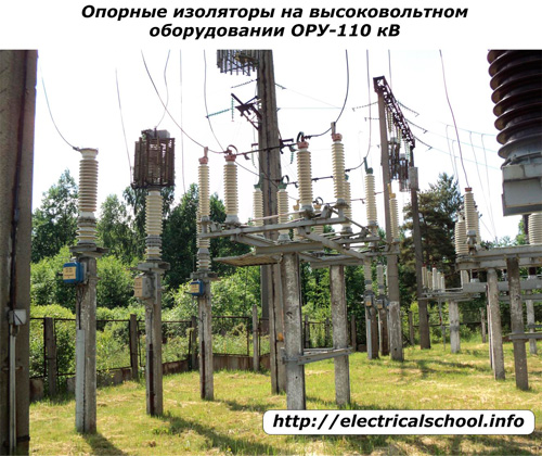
The points of connection of the power lines to the equipment of the 110-kV high-voltage open switchgear are protected by more complex structures of load-bearing insulators that can withstand significant electrical and mechanical loads. They remove the live wires from the supports at an even greater distance.
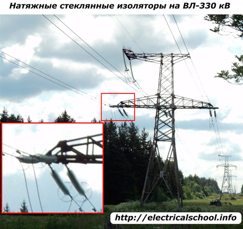
The same can be seen in the photo of an overhead tower made of metal for the transmission of 330 kV high voltage power. The photo shows that each phase has a separation of current conductors, the conductors of which are fixed on the traverse with an even more reinforced wreath of glass tension insulators.
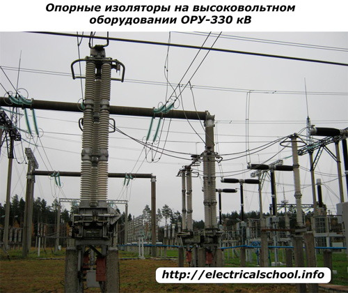
The post insulators of a 330 kV substation move the conductors and busbars even further away from the equipment.
Cable power lines
In these structures, the conductive cores of the phases are separated from each other by a layer of solid dielectric and are protected from the influence of the environment by a strong but elastic shell. Sometimes liquid cable oil made from petroleum products or gaseous substances can be used instead of solids. But such dielectrics are rarely used in practice.
In terms of production costs, cable lines are more expensive than overhead transmission lines. Therefore, they are laid within the city, inside residential buildings, industrial areas, at intersections with water barriers, when aerial supports cannot be installed.
For laying cables, create cable trays, channels or regular ones buried trencheswhich restrict access to live circuits.
Insulation of cable power lines
The construction of the power cable for power lines depends on the amount of power transmitted through it and the applied voltage.
The conductors of the cable are usually made of copper or aluminum alloys, and the type of dielectric materials used between them depends on the magnitude of the applied voltage.
In devices up to 1000 volts, layers of polyethylene compounds or structures with paper fillers and bundles impregnated with cable oil of different consistency are most often used.
The approximate arrangement of the insulation layers for a non-standard four-core cable is shown in the photo.
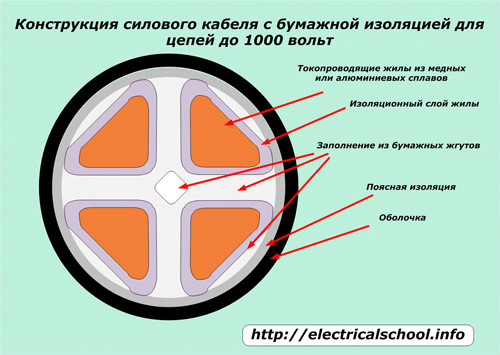
Here, the metal of each conductive core is coated with an insulating layer that comes into contact with the paper bundles and fillers placed in the belt insulation.The outer shell completely seals the entire structure.
When the paper is impregnated with mineral oils with various additives to increase the viscosity of the layer, the dielectric properties increase simultaneously. Such viscous oil-impregnated cable cables can operate in high voltage circuits up to and including 10 kV.
The technical method of manufacturing lead wires increases the operational properties of the dielectric layer. For this, each core is made in the form of a separate coaxial cable with viscous impregnation, placed inside the lead sheath.
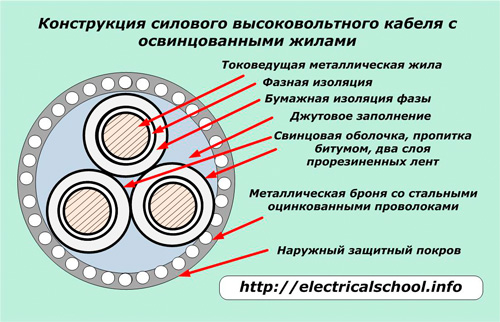
The space between such veins is filled with jute filler and placed inside an armored layer of galvanized steel wires, surrounded by an outer sealed protective layer.
Such cables with lead metal conductors operate in high voltage circuits up to and including 35 kV.
For the transmission of electricity along the cable with higher voltages up to 110 kV and higher, other structures of the insulation layer are used. This can be less viscous cable oil, inert gases (most often nitrogen). Oil pressure in such layers can be low (up to 1 kg / cm2), medium (up to 3 × 5 kg / cm2 ) or high (up to 10-14 kg / cm2 ). Such cables work in high voltage circuits up to and including 500 kV.
Inspections of the insulation of power lines
During the operation of electrical equipment, the state of the dielectric layers is assessed:
-
always;
-
periodically.
Special control devices perform a continuous analysis of the insulation quality in automatic mode. They are tuned in such a way that they measure very low leakage currents during normal operation.When a breakdown of the dielectric layer occurs, these currents increase and the moment of their passage through the critical value is fixed by a relay current circuit with the issuance of an alarm command to notify the service personnel.
Periodic monitoring of the state of insulation of electrical equipment, including power lines, is assigned to specially formed electrical laboratories that carry out high-voltage inspections in the form of measurements and tests with specialized mobile or stationary installations.
The technical staff of such laboratories in the power system is divided into separate departments called insulation service. She, under the direction of the manager, participates in routine tests of the existing energy equipment and power lines and is obliged, before each introduction of any devices on which preventive work with the disassembly of the circuit has been carried out, to submit a written opinion on the readiness of the input section to withstand the high voltage load with insulation.
Read also: Causes of damage to overhead power lines