How to make and implement a small electrical installation project yourself
 In the process of operating electrical installations or improving the operation of equipment, it is sometimes necessary to independently carry out small installation and commissioning works without the participation of specialized organizations that carry out projects of these electrical installations to order with their subsequent installation.
Before starting these works, it is necessary to establish their expediency, then clearly formulate the task, collect initial data, determine the scope of equipment, devices, cable and wiring products, installation materials, etc., think about places to install electrical devices, connect them to the electrical network and emergency modes of operation, electrical safety issues, cost of work.
Designing is a creative process and cannot be strictly regulated, but it is necessary to take into account a number of restrictions and guidelines provided in various normative and reference literature and local conditions for project implementation.This is a series of documents that are basic and determine the entire process of design, installation and operation of electrical equipment: Rules for Electrical Installation (PUE), Construction norms and rules (SNiP), Rules for technical operation (PTE), Safety rules (PTB).
The design itself consists of several mandatory stages. The first is defining and preparing the assignment. The formulation of the problem is carried out by workers of related services — mechanics, technologists, etc. If it concerns the improvement of the electrical installation itself, then the problem statement is carried out by electricians. The task is drawn up after careful consideration of the situation.
The more carefully thought out the task, the more successful the subsequent design and installation. The assignment should reflect the existing situation, the situation, and also prepare detailed sketches, for example, installations, buildings. The task sets a specific task that reflects a real need: increasing productivity and labor safety, saving electricity, water, fuel, etc., improving the quality of level, pressure, temperature control, installing control and signaling equipment in some room, using a certain type of equipment, etc.
For example, in FIG. 1 schematically shows the water supply of the technological nodes in the workshop. There is a constant pressure and water storage tank 1 located on the roof of the building and equipped with an overflow pipe 2. Water enters the tank through the supply pipe 3 from the pump 4. The water level in the tank is monitored by workshop personnel. When the water level approaches the upper limit, the excess water flows through pipe 2 into the sewer.
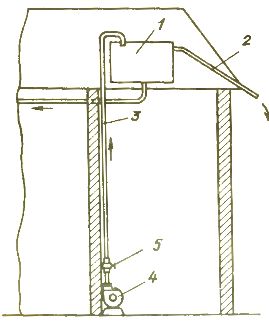
Rice. 1.Water supply system with process water
This system has a number of disadvantages. Here there is a significant excessive consumption of water, since the working staff does not always notice the overflow of the tank, and turning off the pump is not always profitable, since with the constant consumption of water from the tank for technological needs, the level drops and water is lost.
If the pump is not turned off so that it runs continuously and the water supply is regulated by valve 5 on pipeline 4, even with this method there is no guarantee that there will be no water leakage due to the inconsistency of the water flow from the tank. In addition, there is an excess consumption of electricity and wear and tear of the constantly running pump 6.
It is necessary to set the general task of the planned work:
-
to reduce the consumption and excessive consumption of water;
-
reducing power overload;
-
reducing the wear and tear of the pump and its electric motor;
-
improvement of working conditions;
-
not to distract the attention of the staff, workers from performing their main work;
-
improving the quality of the water supply.
As you can see, to this simple water supply system you can set a number of effective goals, the achievement of which will significantly improve the operation and economy of the system.
Initial data collection showed that the installed pump is equipped with a 4A80A2 electric motor with nominal data: rotation speed 2850 rpm, alternating voltage 380 V, 50 Hz, 3.3 A, efficiency-0.81, cosφ = 0.85, Azn = 6 ,5; tank with a capacity of 1.5 m3 (the tank is not grounded), feeding 1 pipeline with a diameter of 42 mm.
After the stages of defining the problem and collecting the initial data, it is necessary to analyze it, outline the desired direction for solving the problem and make a decision.
The problem can be solved by installing a feed pipe level regulator in the tank. But such a solution cannot be considered satisfactory, since, solving the problem of level regulation, we do not at all meet the requirements for saving energy and reducing pump wear.
It is possible to install a control valve on the pipeline with an electric actuator controlled by level sensors in the tank. Here there are disadvantages of the previous method, as well as increased consumption of electrical equipment.
From the discussion of these options, it clearly follows: the level in the tank must be controlled by turning on the pump when the water level drops, and, quite clearly, the turning on must be automatic.
Then it is necessary to formulate the task, i.e. defines the scope of the project. When designing, you should:
1) develop a schematic diagram of the power supply and protection of the electric motor;
2) development of a schematic diagram of the automatic control;
3) development of a schematic alarm diagram;
4) select electrical and control and signaling equipment;
5) prepare plans and types of arrangement of electrical equipment and apparatus;
6) draw up electrical diagrams or, as they are also called, electrical diagrams and connections;
7) select cable and cable products and installation products;
8) if it will not be possible to use standard methods for installing equipment and laying electrical wires, then the corresponding sketches are prepared;
9) place electrical equipment and control and signaling equipment on the floor plan using symbols;
10) prepares a plan for production of work, commissioning of the electrical installation;
11) make an assessment, i.e. determines the cost of equipment and, if necessary, the cost of installation work.
The design itself consists in the development of the composition of the technical means, the work of which corresponds to all points of the requirements of the assignment. The connections (schemes) of these devices must provide the specified algorithms for the operation of the electrical installation with maximum efficiency and safety for personnel. So in this case the power supply scheme was unsatisfactory, it needs to be redesigned.
Let's show the design process in the above sequence, numbered paragraphs.
1. To drive the electric motor, ie. E. for electricity conversion, a starter is needed, for which we take a PME-122 type magnetic starter. The type of starter depends on the rated current of the motor. With our current of 3.3 A, the closest rated current of the starter is 10 A, which is reflected by the first digit in its type.
In addition, since the starter is installed indoors, it must have a protective case - this is number 2 in the type of starter (in parallel, we will inform you that 1 is a starter without a case, 3 is protected from dust, the degree of protection is IP54).
In addition, the electric motor must have overload protection, and this is done using an electric thermal relay. The starter has such a relay, its type is TRN-10.The presence of thermal protection in the starter type is reflected by the third digit, in this case — 2 (1 — non-reversible starter without protection, 2 — irreversible with protection, 3 — reversible without protection, 4 — reversible with protection).
We choose the standard current of the thermal relay — 4 A, i.e. the nearest greater than the motor current. Since the relay has the ability to regulate the operating current within small limits, we put in the project an indication of the value of such regulation in accordance with the load current during normal operation of the electric motor.
In addition to this type, there are other appetizers, for example PML series with built-in electric thermal relays RTL. In our case, it would be possible to use a PML-121002V starter, but it does not meet some requirements on the part of the control circuit, which will be discussed in paragraph 3 of the project.
In addition, the supply line of the pump also needs protection against short-circuit currents, as well as a device that makes it possible to disconnect the starter and the electric motor from the supply network if necessary. These requirements can be met with a circuit breaker such as type AP50B-ZMby connecting it in series with the starter on the supply side.
The developed scheme, as a rule, is drawn on paper (Fig. 2).
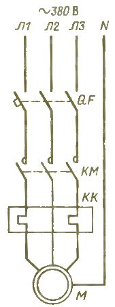
Rice. 2. Pump power supply diagram
Since overload protection is provided by the starter, the circuit breaker will provide protection against short circuit currents.Taking into account the operating current of the motor and the current of the thermal relay of the starter, the rated current of the breaker should be at least 4-6 A, and to compensate for the current of the thermal relay, the tripping current of the release should be a step or two higher.
Since the rated current of the AP50B -ZM circuit breaker is 50 A, it meets the necessary requirements, and the operating current of the current release is taken on a scale of standard values of -10 A.
2. A schematic diagram for automatic pump control is developed based on typical and generally accepted schemes.
For example, in FIG. 3 and shows a diagram of manual control carried out using the «Start» (open contact) and «Stop» (open contact) buttons.
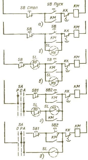
Rice. 3. Design of the control scheme
When the «Start» button is pressed, the voltage through the closed contact of the «Stop» button is supplied to the coil of the starter KM, which is activated and closes its contacts. One of the contacts is connected in parallel with the «Start» button, therefore, after releasing this button, the power supply to the coil will be provided through this contact, called the auxiliary contact.
To turn off the starter, the «Stop» button is pressed, the contact of which opens and interrupts the supply circuit of the coil, which releases its contacts.
For the purposes of automation, it is possible to connect the lower level contact of the NU SL level sensor in parallel with the SB2 button (Fig. 3, b).
When the water reaches the LP level, the sensor will turn on the starter and the pump. However, in this scheme there is no automatic shutdown of the pump when the water level rises above the OU mark. Therefore, it is necessary to insert the second contact of the SL sensor into the control circuit.It is clear that this contact must be open, and since its action is similar to the «Stop» button, then we connect it sequentially to such a button (Fig. 3, c).
In this scheme, manual and automatic controls are combined in common electrical circuits. However, this is inconvenient and such duplication is not rational, therefore, as a rule, such chains are split. Separation is done with a switch. The corresponding diagram is shown in fig. 3, d.
The introduced SA switch has three switch positions — manual control (P), off (O) and automatic control (L). Position O is necessary to disable the circuit during repairs, breakdowns and other cases, one of which is described below.
The above scheme is used when there is a suitable range between the controlled parameters, in this case the level, for example, 0.5-1 m. This scheme avoids starting the pump too often. It can also be used for other purposes, for example to regulate the room temperature.
But in our case, the level in the tank must be maintained at one level, and the indicated scheme can be simplified, since in this case it will be unnecessarily complicated technically due to the larger number of sensors. This drawback can be avoided if the designed scheme is tied to the characteristics of the equipment used.
For example, a certain gain can be achieved using an RP-40 type float level switch. The relay contains in its design mercury switches, which are switched with a certain delay, due to the time of mercury pouring into the contact device. This makes it possible to achieve the relay failure in a small range, which is necessary.In this case, it is 20-25 mm, which satisfies the accuracy of maintaining the level in accordance with the technological requirements of production.
If you use other level sensors, for example DPE or ERSU, they are triggered immediately, and to prevent frequent starting of the pump, it would be necessary to introduce a time relay in the control circuit to delay the response, and this is already a complication of the circuit. Therefore, the skillful selection of equipment allows solving many problems already at the design stage.
The diagram with the RP-40 float relay is shown in fig. 3, e. Here it is necessary to explain the change in the switching positions of the SA switch. The fact is that a suitable PKP10-48-2 type switch accepted for installation has the contact closures shown in fig. 3, e and is not the same as was originally assumed in the development of the circuit of FIG. 3, d. But both schemes for closing switch contacts are functionally equivalent.
Next, you need to provide an alarm circuit. In this case, an emergency situation is a pump failure when the water level in the tank falls below the permissible level. We receive the sound signaling through a call, for example, from the ZP-220 type.
Since it has to react to a decrease in level, ie. to close the contact of the SL sensor, as well as the contact of the KM starter, the circuit here will be the simplest and will consist of series-connected contacts of the sensor and the open contact of the KM starter. Now all the developed schemes can be summarized in one drawing (Fig. 4), which is a schematic circuit diagram of the electrical equipment and automatic control of the pump of the water supply system.
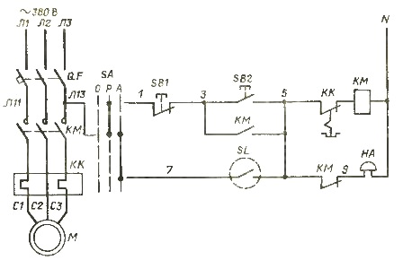
Rice. 4.Scheme of power supply and control of the pump
All circuits in the diagram between contacts and devices are marked with numbers 1,3, 5, etc. The diagram shows that it uses auxiliary contacts of the KM starter - one mark and one break. But since PML series starters up to 10 A have only one such contact — closing or opening, and it is impractical to introduce an intermediate relay into the control circuit due to its complexity, in this case a starter with a large number of auxiliary contacts should be adopted for installation and for this purpose the PME series starter which was selected earlier is suitable. Other starters of the required design can be used. The SB button can be accepted as PKE 722-2UZ.
3. The third stage of design is not separated into a separate because of its simplicity and unity of the circuit with the control circuit.
4. The selection of electrical equipment on the developed circuit, as was shown, can be done already in the process of developing circuits, which allows the most complete use of their functionality and the development of simple and economical circuits that make the most of all possibilities of the equipment.
Another option is also possible: the selection of equipment according to ready-made schemes. But this approach sometimes leads to technical complications, for example, to an increase in the number of intermediate relays due to overspending of contacts in circuits in a purely theoretical design. It follows that before proceeding with the design, it is necessary to carefully study the characteristics, design and capabilities of the electrical equipment.This is necessary in the design of more complex circuits, when it is not possible in the design process to outline specific types of electrical equipment in parallel and intuitively.
5. In addition, based on the specific location and location of the technological equipment, access roads to it and the locations of the proposed location of electrical equipment, plans and types of arrangement of electrical equipment and equipment are drawn up.
In this case, the plan would be extremely simple and not carry maximum information. Therefore, it is more expedient to draw a frontal view of the wall of the room near the pump, where everything designed is located, auxiliary installation products are depicted, for example, distribution boxes, as well as routes for electrical wiring (Fig. 5) . A float relay RP-40 is mounted on the tank (Fig. 5).
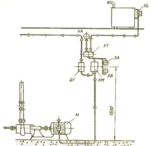
Rice. 5. Installation diagram
6. Diagrams of connections and connections carry information of a purely practical nature about how and with what wiring to connect the clamps of electrical equipment. They are compiled on the basis of schematic diagrams and in the process of actual field wiring are used as a basic document, and schematic diagrams act at this point as a reference and are used when ambiguities arise. All the schematics taken together then serve as operational documentation.
The diagram for our example is shown in Fig. 6. Wiring diagrams of all designed electrical devices and clamps for connecting external wires are shown here. According to the circuit diagram in fig. 4, the clamps of these devices are connected.In the process of connection, the shortest paths for laying electrical wires, the need for stretching and distribution boxes are revealed.
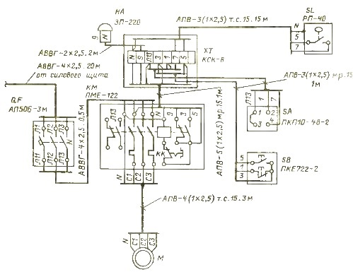
Rice. 6. Wiring diagram of electrical equipment
In fig. 6, the need for a junction box arose in connection with the need for inter-hardware connections, since the cable connections must be made under the bolt brackets. This is due to the fact that aluminum wires will be used, the soldering of which is difficult and even impossible for small cross-sections, and in addition, the bolted connections are made quickly and allow various reconnections in the future for inspections and maintenance.
Since seven clamps were required for the connections, a KSK-8 type junction box with eight dustproof double-sided clamps (protection degree IP44) is adopted for installation. At the end of the design of the connections between the devices, cable lines that contain the required number of cores are identified.
In this case, it is necessary to take into account some other requirements. For example, as already mentioned, the water tank is not grounded. However, now, in connection with the installation of an electrical apparatus on it — the RP-40 relay, the tank must be grounded in accordance with electrical safety requirements.
Earthing can be done with a special earthing wire made of round steel with a diameter of 6 mm, connected to the workshop earthing circuit.
Another way is possible — since the RP-40 relay does not consume electricity and is a control device, to ground it, you can use the ground loop of the power source (transformer substation), and the wire here will be the neutral wire of the electrical network and the earth will already be disappearing — also an effective measure of protection against electric shock. To do this, in the wiring between the XT box and the SL relay, we provide a third wire, on one side connected to neutral and on the other to the relay body.
7. At the end of drawing up diagrams, specific types of wiring are selected - brands of wires and cables, methods of their laying, lengths are measured on the floor plan or in kind, and all this is applied to the drawing. The cross-section is selected according to the PUE for the long-term permissible load current, the carrying capacity of the cable must be higher than the load current, in this case more than the motor current.
From the starter to the electric motor, the wiring must be protected from mechanical damage, which is usually done with an electrically welded steel pipe with a wall thickness of at least 2 mm.
A steel pipe, as a rule, is laid on the walls in places subject to mechanical loads and damage, and in all other places, as well as in the concrete floor, as in our example, plastic pipes of the appropriate diameter are used. For small distances it is permissible to use a single piece of steel pipe.
The electrical wiring from the starter to the XT box is done with wires in a metal hose laid along the wall with clamps. Wiring to the button and switch is done the same way.You can put a cable to the conversation.
As for the electrical wiring to the tank level sensor, here we definitely accept wires in steel pipes, as this is a requirement for electrical wiring placed on the ceiling for fire safety purposes, since the tank is located on the ceiling of the workshop.
8. Wiring in the workshop is laid along simple routes and without any structural features, therefore no special drawings are required.
9. Compilation of the type of arrangement of electrical equipment has already been carried out earlier, and the plan in this case would be the simplest, therefore it does not need a special drawing. Electrical equipment and wiring layouts indicating installation locations and methods are intended for a larger number of equipment—as shown in the following design example.
10. The plan for the production of work and commissioning of the electrical installation must at least determine the sequence of work, for example, determine the time of work without affecting the workshop, the number of electricians, the process of setting up the control scheme, testing of the installed electrical installation, trial operation, handover to the workers in the workshop, etc.
11. Before preparing an estimate, it is necessary to prepare a specification of electrical equipment and materials. The completed project is subject to approval.