The device of overhead power lines with different voltage
The transportation of electrical energy over medium and long distances is most often carried out via power lines located in the open air. Their design must always meet two main requirements:
1. High power transmission reliability;
2. Ensuring safety for people, animals and equipment.
During operation under the influence of various natural phenomena associated with hurricane gusts of wind, ice, frost, power lines are periodically subjected to increased mechanical load.

For a comprehensive solution to the problems of safe transportation of electrical energy, power engineers must raise the power wires to a great height, distribute them in space, isolate them from building elements and install them with current wires with increased cross-sections on high supports for strength.
General arrangement and layout of overhead power lines
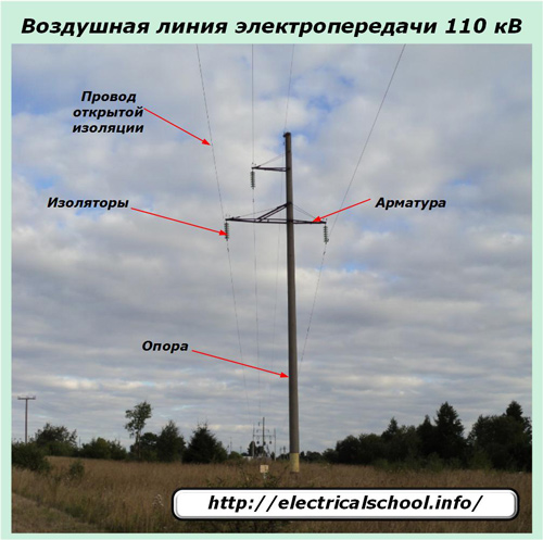
Schematically, any power transmission line can be represented:
-
supports installed in the ground;
-
wires through which current flows;
-
linear fittings mounted on supports;
-
insulators fixed to the armature and maintaining the orientation of the wires in the air.
In addition to the elements of overhead lines, it is necessary to include:
-
foundations for supports;
-
lightning protection system;
-
grounding devices.
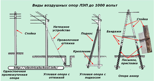
The supports are:
1. anchoring designed to withstand the forces of the tensioned wires and equipped with tensioning devices on the fittings;
2. intermediate, used to secure the wires through the supporting clamps.
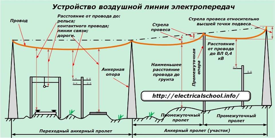
The distance on the ground between two anchor supports is called the anchor section or span, and for intermediate supports between each other or with an anchor - intermediate.
When an overhead power line passes through water barriers, engineering structures or other critical objects, then supports with wire tensioners are installed at the ends of such a section, and the distance between them is called an intermediate anchor section.
The wires between the supports are never pulled like a string—in a straight line. They always sag slightly being in the air, taking into account the weather conditions. But at the same time, the safety of their distance from ground objects should be taken into account:
-
rail surfaces;
-
contact wires;
-
transport highways;
-
wires of communication lines or other overhead lines;
-
industrial and other facilities.
The hanging of the wire from the tensioned state is called hanging arrow… It is estimated in different ways between supports, because their tops can be located at the same level or with elevations.
The sag relative to the highest support point is always greater than that of the lower one.
The dimensions, length and construction of each type of overhead transmission line depend on the type of current (alternating or direct) of electrical energy transported through it and the magnitude of its voltage, which can be less than 0.4 kV or reach 1150 kV.
Wire arrangement of overhead lines
Since electric current only flows in a closed loop, consumers are powered by at least two wires. According to this principle, simple overhead lines are created with single-phase alternating current with a voltage of 220 volts. More complex electrical circuits transfer energy in a three- or four-wire circuit with a rigidly insulated or grounded zero.
The diameter and metal for the wire are selected for the design load of each line. The most common materials are aluminum and steel. They can be made as a single monolithic conductor for low-voltage circuits or woven from multi-wire structures for high-voltage transmission lines.
The internal inter-wire space can be filled with neutral grease, which increases heat resistance or not.
Multi-wire constructions made of aluminum conductors that carry good current are created with steel cores that are designed to take mechanical stress and prevent breakage.
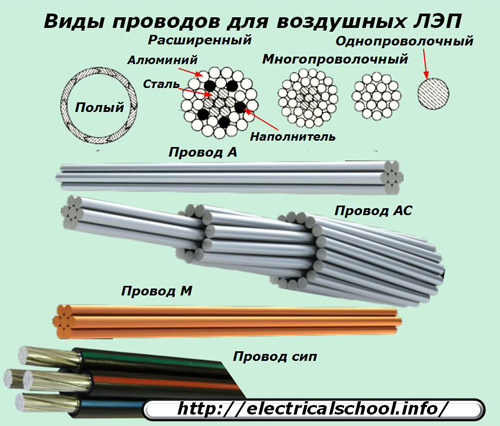
GOST provides a classification of open conductors for overhead power lines and determines their marking: M, A, AC, PSO, PS, ACKC, ASKP, ACS, ACO, ACS. In this case, single-wire wires are indicated by the size of the diameter. For example, the abbreviation PSO-5 reads "steel wire made with a single core with a diameter of 5 mm.» Multi-conductor wires for power lines use a different marking, including a two-digit designation written as a fraction:
-
the first is the total cross-sectional area of the aluminum wires in mm sq.;
-
the second is the cross-sectional area of the steel insert (mm sq).
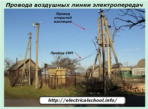
In addition to open metal conductors, conductors are increasingly used in modern overhead lines:
-
self-supporting insulation;
-
protected by an extruded polymer that prevents the occurrence of short circuits when the phases are swept by the wind or when foreign objects are thrown from the ground.
VL v self-supporting self-supporting insulated conductors are gradually replacing old non-insulated structures. They are increasingly used in internal networks made of copper or aluminum cores covered with rubber with a protective layer of dielectric fibrous materials or PVC compounds without additional external protection.
In order to exclude the occurrence of corona discharge with a long length, wires with VL-330 kV and higher voltage are divided into additional flows.
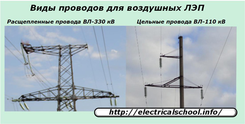
On the VL-330, two conductors are installed horizontally, on the 500 kV line they increase to three and are placed at the vertices of an equilateral triangle. For overhead lines of 750 and 1150 kV, a separation of 4, 5 or 8 streams is used, respectively, located at the corners of their own equilateral polygons.
The formation of "corona" leads not only to energy losses, but also distorts the shape of the sinusoidal oscillation. Therefore, they fight it using constructive methods.
Supporting device
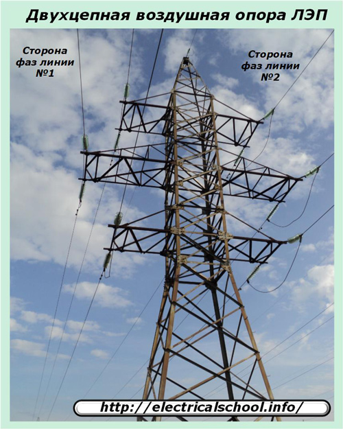
Supports are usually created to secure the wires of an electrical circuit.But on parallel sections of two lines, one common support can be used, which is intended for their joint installation. Such constructions are called double-circuit.
The material for the production of supports can be:
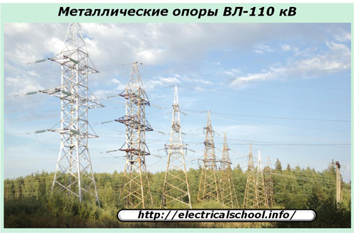
1. profiled corners of different brands of steel;
2. construction timber logs impregnated with anti-rotting compounds;
3. reinforced concrete structures with reinforced bars.
Supporting structures made of wood are the cheapest, but even with good impregnation and proper maintenance, they serve no more than 50 ÷ 60 years.
According to the technical project, the supports of overhead lines above 1 kV differ from low-voltage ones in their complexity and the height of the attachment of the wires.
They are made in the form of oblong prisms or cones with a wide base at the bottom.
Each support structure is calculated for mechanical strength and stability, there is sufficient structural reserve for the existing loads. But it should be borne in mind that during operation, violations of its various elements are possible as a result of corrosion, impact, non-compliance with the installation technology.
This leads to a weakening of the rigidity of a single structure, deformations and sometimes falling of the supports. Often such cases occur at those times when people work on the supports, dismantle or pull wires, creating variable axial forces.
For this reason, the acceptance of a team of installers to work at a height from the supporting structure is carried out after checking their technical condition with an assessment of the quality of its buried part in the ground.
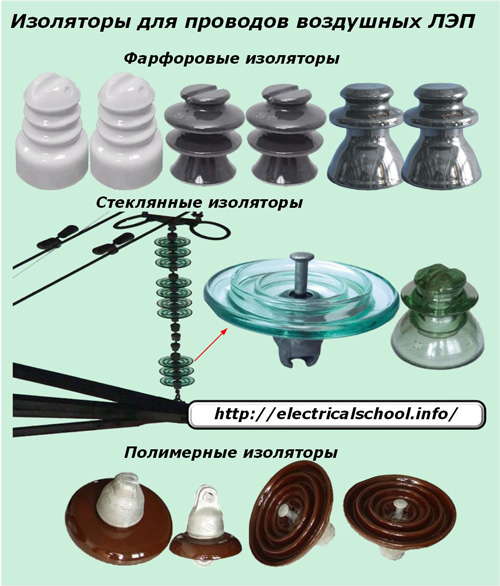
Isolation device
On overhead power lines, products made of materials with high dielectric properties with resistance ÷ Ohm. M. They are called insulators and are made of:
-
porcelain (ceramics);
-
glass;
-
polymeric materials.
The design and dimensions of the insulators depend on:
-
on the magnitude of the dynamic and static loads applied to them;
-
the values of the effective voltage of the electrical installation;
-
operating conditions.
The complex shape of the surface, working under the influence of various atmospheric phenomena, creates an increased path for the flow of a possible electric discharge.
Insulators installed on overhead lines for fixing wires are divided into two groups:
1. pin;
2. suspended.
Ceramic models
Porcelain or ceramic pins with single insulators have found greater application on overhead lines up to 1 kV, although they work on lines up to and including 35 kV. But they are used under the condition of fastening wires with a low cross-section, creating small pulling forces.
Garlands of suspended porcelain insulators are installed on 35 kV lines.
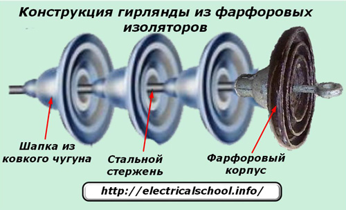
The Single Porcelain Suspension Insulator Kit includes a dielectric body and cap made of malleable iron. Both parts are held together by a special steel rod. The total number of such elements in the garland is determined by:
-
the voltage value of the overhead line;
-
supporting structures;
-
features of equipment operation.
As the grid voltage increases, the number of insulators in the string is added. For example, for 35 kV overhead lines, it is enough to install 2 or 3 of them, and for 110 kV, 6 ÷ 7 are already needed.
Glass insulators
These designs have a number of advantages over porcelain:
-
the absence of internal defects in the insulating material that affect the formation of leakage leaks;
-
increased strength to torsional forces;
-
transparency of the structure, which allows visual assessment of the condition and observation of the polarization angle of the light flux;
-
lack of signs of aging;
-
less loads than your own weight;
-
automation of production and smelting.
The disadvantages of glass insulators are:
-
weak anti-vandal resistance;
-
low impact strength;
-
the possibility of damage during transportation and installation by mechanical forces.
Polymer insulators
They have increased mechanical strength and weight, reduced by up to 90% compared to ceramic and glass counterparts. Additional benefits include:
-
ease of installation;
-
greater resistance to pollution from the atmosphere, which, however, does not exclude the need for periodic cleaning of their surface;
-
hydrophobicity;
-
good susceptibility to overvoltage;
-
increased vandal resistance.
The durability of polymer materials also depends on the operating conditions. In an air environment with increased pollution from industrial enterprises, polymers can exhibit "brittle fracture" phenomena, which consist in a gradual change in the properties of the internal structure under the influence of chemical reactions from pollutants and atmospheric moisture occurring in combination with electrical processes.
When vandals shoot polymer insulators with a shot or bullet, there is usually no complete destruction of the material, such as glass. Most often, the pellet or bullet flies straight through or lodges in the body of the skirt. But the dielectric properties are still underestimated and damaged elements in the garland require replacement.
Therefore, such equipment should be periodically checked by visual inspection methods. And it is almost impossible to detect such damage without optical tools.
Air line fittings
For fixing insulators on an overhead line support, assembling them into garlands and installing live wires to them, special fasteners are produced, which are usually called fittings.
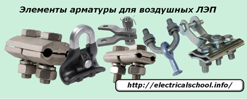
According to the tasks performed, the fittings are classified into the following groups:
-
a connector designed to connect suspension elements in different ways;
-
tensioning, which serves to attach tensioning brackets to wires and garlands of anchor supports;
-
supporting, carrying out the retention of fasteners of wires, loops and nodes of screens;
-
protective designed to preserve the operation of overhead line equipment when exposed to atmospheric discharges and mechanical vibrations;
-
connectors consisting of oval connectors and thermite cartridges;
-
contact;
-
spiral;
-
installation of pin insulators;
-
installation of self-supporting insulated wires.
Each of the listed groups has a wide assortment of details and requires more careful study. For example, only protective fittings include:
-
protective horns;
-
rings and screens;
-
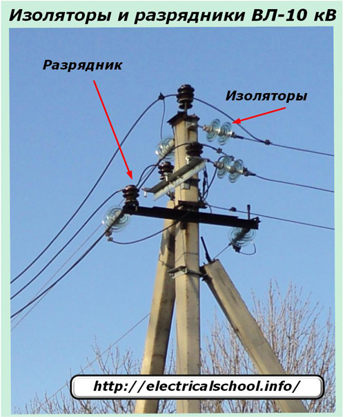
arresters;
-
vibration dampers.
Protective horns create a spark gap, divert the resulting electric arc when insulation occurs and thus protect overhead line equipment.
The rings and screens divert the arc from the surface of the insulator, improve the distribution of voltage over the entire area of the string.
Surge arresters protect equipment from surges generated by lightning.They can be used on the basis of tube structures made of vinyl plastic or fiber-bakelite tubes with electrodes, or they can be made of valve elements.
Vibration dampers work on ropes and wires, prevent damage from fatigue stresses caused by vibrations and vibrations.
Grounding devices of overhead lines
The need for re-earthing overhead line supports is caused by the requirements for safe operation in case of emergency modes and lightning surges. The loop resistance of the grounding device must not exceed 30 ohms.
For metal supports, all fasteners and reinforcement must be connected to the PEN wire, and for reinforced concrete, a combined zero connects all supports and reinforcement of the supports.
On supports made of wood, metal and reinforced concrete, pins and hooks during the installation of self-supporting insulated insulated wires are not grounded, except in cases where it is necessary to carry out repeated grounding for protection against overvoltage.
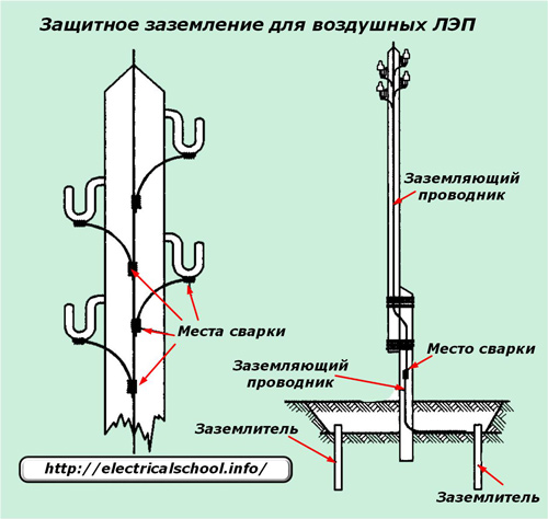
The hooks and pins mounted on the support are connected to the ground loop by welding using a steel wire or rod with a diameter not thinner than 6 mm with the mandatory presence of an anti-corrosion coating.
Metal reinforcement is used on reinforced concrete supports for grounding. All contact connections of the ground wires are welded or tightened in a special bolt.
The supports of overhead power lines with a voltage of 330 kV and more are not grounded due to the complexity of implementing technical solutions to ensure a safe magnitude of contact and step voltage.In this case, protective earthing functions are assigned to high-speed lines.