SMD resistors — types, parameters and characteristics
A resistor is an element that has some kind of resistance; it is used in electronics and electrical engineering to limit current or obtain the required voltage (for example, using a resistive divider). SMD resistors are surface mount resistors, in other words, surface mount resistors.
The main characteristics of resistors are the nominal resistance, measured in ohms, and it depends on the thickness, length and materials of the resistive layer, as well as the power dissipation.
Surface mount electronic components are distinguished by their small dimensions due to the fact that they either do not have connection terminals in the classical sense. Bulk installation items have long leads.
Previously, when assembling electronic equipment, they connected the circuit components to each other (hinged assembly) or passed them through the printed circuit board into the corresponding holes. Structurally, their conclusions or contacts are made in the form of metallized pads on the body of the elements.In the case of microcircuits and surface mount transistors, the elements have short, rigid "legs".
One of the main characteristics of SMD resistors is their size. This is the length and width of the box, according to these parameters, elements are selected that correspond to the layout of the board. Usually, the dimensions in the documentation are written in abbreviated form with a four-digit number, where the first two digits indicate the length of the element in mm, and the second pair of characters indicates the width in mm. However, in reality, the dimensions may differ from the markings depending on the types and series of elements.
Typical sizes of SMD resistors and their parameters
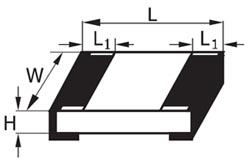
Figure 1 — designations for decoding standard sizes.
1. SMD resistors 0201:
L = 0.6 mm; W = 0.3 mm; H = 0.23 mm; L1 = 0.13 m.
-
Rating range: 0 Ohm, 1 Ohm — 30 MΩ
-
Permissible deviation from nominal: 1% (F); 5% (J)
-
Rated power: 0.05W
-
Operating voltage: 15V
-
Maximum allowable voltage: 50 V
-
Operating temperature range: –55 — +125 ° C
2. SMD resistors 0402:
L = 1.0 mm; W = 0.5 mm; H = 0.35 mm; L1 = 0.25 mm.
-
Rating range: 0 Ohm, 1 Ohm — 30 MΩ
-
Permissible deviation from nominal: 1% (F); 5% (J)
-
Rated power: 0.062W
-
Operating voltage: 50V
-
Maximum allowable voltage: 100 V
-
Operating temperature range: –55 — +125 ° C
3.SMD resistors 0603:
L = 1.6 mm; W = 0.8 mm; H = 0.45 mm; L1 = 0.3 mm.
-
Rating range: 0 Ohm, 1 Ohm — 30 MΩ
-
Permissible deviation from nominal: 1% (F); 5% (J)
-
Nominal power: 0.1W
-
Operating voltage: 50V
-
Maximum allowable voltage: 100 V
-
Operating temperature range: –55 — +125 ° C
4. SMD resistors 0805:
L = 2.0 mm; W = 1.2 mm; H = 0.4 mm; L1 = 0.4 mm.
-
Rating range: 0 Ohm, 1 Ohm — 30 MΩ
-
Permissible deviation from nominal: 1% (F); 5% (J)
-
Rated power: 0.125W
-
Operating voltage: 150V
-
Maximum allowable voltage: 200 V
-
Operating temperature range: –55 — +125 ° C
5. SMD resistors 1206:
L = 3.2 mm; W = 1.6 mm; H = 0.5 mm; L1 = 0.5 mm.
-
Rating range: 0 Ohm, 1 Ohm — 30 MΩ
-
Permissible deviation from nominal: 1% (F); 5% (J)
-
Nominal power: 0.25W
-
Operating voltage: 200V
-
Maximum allowable voltage: 400 V
-
Operating temperature range: –55 — +125 ° C
6. SMD resistors 2010:
L = 5.0 mm; W = 2.5 mm; H = 0.55 mm; L1 = 0.5 mm.
-
Rating range: 0 Ohm, 1 Ohm — 30 MΩ
-
Permissible deviation from nominal: 1% (F); 5% (J)
-
Nominal power: 0.75W
-
Operating voltage: 200V
-
Maximum allowable voltage: 400 V
-
Operating temperature range: –55 — +125 ° C
7. SMD resistors 2512:
L = 6.35 mm; W = 3.2 mm; H = 0.55 mm; L1 = 0.5 mm.
-
Rating range: 0 Ohm, 1 Ohm — 30 MΩ
-
Permissible deviation from nominal: 1% (F); 5% (J)
-
Nominal power: 1W
-
Operating voltage: 200V
-
Maximum allowable voltage: 400 V
-
Operating temperature range: –55 — +125 ° C
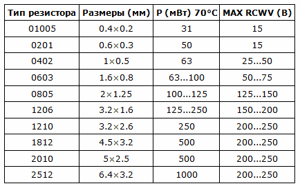
As you can see, as the size of the chip resistor increases, the nominal power dissipation increases in the table below, this dependence is more clearly shown, as well as the geometric dimensions of other types of resistors:
Table 1 — Marking of SMD resistors
Depending on the size, one of three types of resistor rating marking may be used. There are three types of markings:
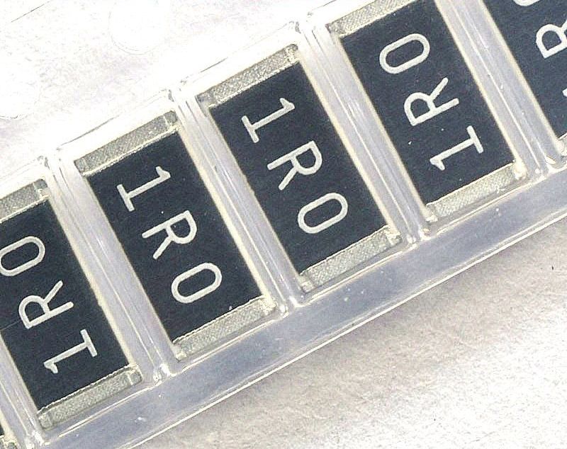
1. With 3 digits. In this case, the first two mean the number of ohms, and the last number zeros. This is how resistors of the E-24 series are designated, with a deviation from the nominal value (tolerance) of 1 or 5%. The standard size of resistors with this marking is 0603, 0805 and 1206. Example of such a marking: 101 = 100 = 100 Ohm

Figure 2 is an image of an SMD resistor with a nominal value of 10,000 Ohm, also known as 10 kOhm.
2. With 4 characters. In this case, the first 3 digits indicate the number of ohms, and the last is the number of zeros. This is how resistors of the E-96 series with standard sizes 0805, 1206 are described. If the letter R is present in the marking, it plays the role of a comma separating whole numbers from fractions. Thus, the marking 4402 means 44,000 ohms or 44 kOhm.

Figure 3 — Image of a 44 kΩ SMD resistor
3. Marking with a combination of 3 characters — numbers and letters. In this case, the first 2 characters are numbers indicating the coded resistance value in ohms. The third sign is the multiplier. Thus, standard size 0603 resistors are marked from the E-96 series resistors, with a tolerance of 1%. The translation of letters into a factor is carried out in the following order: S = 10 ^ -2; R = 10^-1; B = 10; C = 10 ^ 2; D = 10^3; E = 104; F = 10^5.
The decoding of the codes (the first two characters) is carried out according to the table shown below.
Table 2 — decoding codes for marking SMD resistors
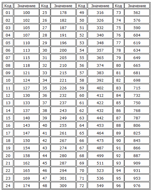

Figure 4 — a resistor with a three-digit marking 10C, if you use the table and the given number of factors, then 10 is 124 Ohm, and C is a factor of 10 ^ 2, which is equal to 12 400 Ohm or 12.4 kOhm.
The main parameters of resistors
In an ideal resistor, only its resistance is considered. In reality, the situation is different — resistors also have parasitic inductive-capacitive components.Below is one option for an equivalent resistor circuit:
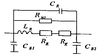
Figure 5 — Equivalent resistor circuit
As you can see in the diagram, there are both capacitors (capacitors) and inductance. Their presence is due to the fact that each conductor has a certain inductance, and a group of conductors has parasitic capacitance. In a resistor, these are related to the location of its resistive layer and its design.
These parameters are usually not taken into account in DC and low-frequency circuits, but they can have a significant influence in high-frequency radio transmission circuits and in switching power supplies, where currents flow with frequencies from tens to hundreds of kHz. In such circuits, any parasitic component, in the flesh of the improper wiring of the conductive paths of the printed circuit board, can make it impossible to work.
So, inductance and capacitance are elements that affect impedance and the edges of currents and voltages as a function of frequency. The best in terms of frequency characteristics are the surface mount elements, due to their exact same small size.
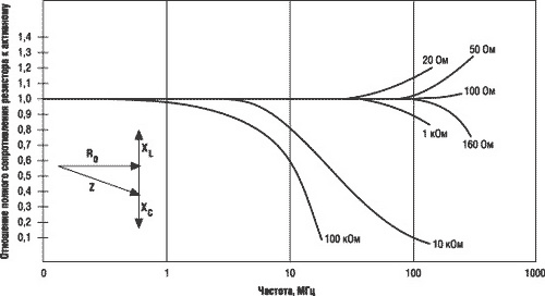
Figure 6 — The graph shows the ratio of the total resistance of the resistor to the active resistance at various frequencies
Impedance includes both active resistance and parasitic inductance and capacitance reactances. The graph shows a drop in impedance with increasing frequency.
Resistor design
Surface mount resistors are inexpensive and convenient for automated assembly of electronic devices on a conveyor. However, they are not as simple as they seem.
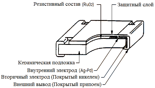
Figure 7 — Internal structure of the SMD resistor
The resistor is based on a substrate of Al2O3 — aluminum oxide.It is a good dielectric and a material with good thermal conductivity, which is equally important, since during operation all the power of the resistor is released into heat.
As a resistive layer, a thin metal or oxide film is used, for example chromium, ruthenium dioxide (as shown in the picture above). The characteristics of resistors depend on the material from which this film is composed. The resistive layer of individual resistors is a film up to 10 microns thick, made of a material with a low TCR (temperature coefficient of resistance), which gives high temperature stability of parameters and the possibility of creating high-precision elements, an example of such a material is constantan, but the ratings of such resistors rarely exceed 100 ohms.
Resistor pads are formed from a set of layers. The inner contact layer is made of expensive materials such as silver or palladium. The intermediate is made of nickel. And the outer one is lead tin. This design is due to the need to ensure high adhesion (cohesion) of the layers. The reliability of contacts and noise depend on them.
In order to reduce parasitic components, they arrive at the following technological solutions when forming a resistive layer:
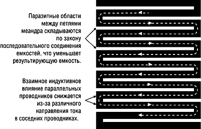
Figure 8 — The shape of the resistive layer
The installation of such elements is carried out in furnaces and in radio amateur workshops using a soldering iron, that is, with a stream of hot air. Therefore, during their production, attention is paid to the temperature curve of heating and cooling.
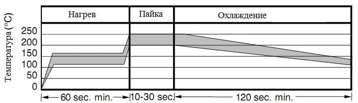
Figure 9 — heating and cooling curve when soldering SMD resistors
conclusions
The use of surface-mounted components had a positive effect on the weight and dimensions of the electronic equipment, as well as on the frequency characteristics of the element. Modern industry produces most of the common elements in SMD designs. Including: resistors, capacitors, diodes, LEDs, transistors, thyristors, integrated circuits.