Rules for reading electric circuits with electronic elements
Electronic devices and devices are widely introduced in modern control and automation schemes. This circumstance somewhat complicates the reading of such schemes, since it requires knowledge of the peculiarities of their construction and some features when reading them. To read a chart that has electronic devices, it is necessary to have certain knowledge in the field of elementary theory of electronic circuits.
First of all, it is necessary to clearly imagine the mechanism of passage of electric charges through various elements of the circuits used in the electronics of the devices. A good understanding of the purpose and principle of operation of the control elements in them is necessary. Thus, reading electronic circuits is much more difficult. reading electrical diagrams.

In circuits with electronic components, there are always several separate circuits. Each of them is designed for a certain voltage, which is created either by separate sources of electricity, or a common source is used for all circuits through the appropriate voltage divider.Otherwise, the voltage for each of the circuits is obtained by connecting them to the voltage dividerto resistors of different rating connected in series in the source circuit.
Since the power supply to the main circuits in electronic devices is assumed to be single-wire, many schematics do not depict a return wire. Instead, they introduce symbols to connect the end of the circuit to the body of the apparatus. The housings of electronic devices are usually grounded, the connection to the housing is indicated in the schematics as grounding.
Here we limit ourselves to an analysis of only the schematic diagrams of some simple electronic devices. Similar schemes can be encountered by electricians, electricians and electricians when servicing various industrial installations.
Schematics containing electronic devices include multiple schematics, which makes these schematics much more difficult to read. To read a schematic of any complex electronic device, you need to be able to break it down into parts (rectifier, low and high frequency amplifier, filters, etc.), and this requires a high degree of skill. To be well versed in complex circuits, you need to master reading the diagrams of individual elements that make up a complex circuit. Therefore, we will first consider the simplest schemes.
So, in fig. 1 shows a diagram of a full-wave rectifier in which two diodes VD1 and VD2 are used as valves. The primary winding of the power transformer T has three terminals, which allows the transformer to be used for three primary single-phase voltages: 220, 127 and 110 V.
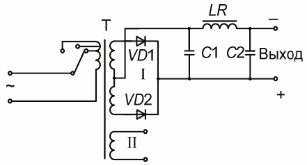
Rice. 1. Schematic diagram of a full-wave rectifier
The transformer has two secondary windings: power I (the number of turns of this winding is selected depending on the required value of the rectified voltage) and winding II for powering the signal lamp circuit. To reduce the ripple of the rectified voltage, a U-shaped smoothing filter consisting of capacitors C1, C2 and inductor LR is included in the circuit.
In fig. 2 shows a three-phase bridge rectifier circuit using semiconductor valves. The circuit consists of six semiconductor diodes forming two groups (VD1, VD2, VD3 and VD4, VD5, VD6). Two diodes are connected to each phase, with opposite ends. As a result, when the current passes through one phase diode, the other turns out to be locked.
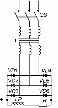
Rice. 2. Schematic diagram of a three-phase bridge rectifier
As follows from the diagram, the diodes of each group are connected in parallel and, as is known from the theory, the current flows through the diode that will have the greatest positive potential at the moment. Thus, one of the groups (diodes VD4, VD2 and VD3) is the plus of the rectifier, and the other (diodes VD4, VD5 and VD6) is its minus.
At the output of the rectifier there is an inductive smoothing filter — LR, included in the cut of the output wire. The purpose of the filter is to create an inductive resistance for the alternating component of the rectified current and thereby reduce its value.
In fig. 3 shows a schematic diagram of a two-stage transistor amplifier. It follows from the diagram that the amplifier is powered by a single-phase alternating current network through a transformer T1 and a push-down rectifier VD. The positive pole of the output voltage is fed to the housing, and the negative pole is fed to the voltage dividers R1 — R2 and R4 — R5.Each of these splitters is connected to the chassis (ie the positive pole of the power supply).
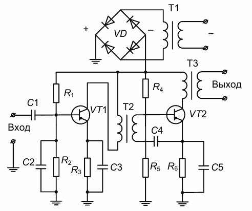
Rice. 3. Schematic diagram of a two-stage transistor amplifier
Amplification is carried out using two transistors VT1 and VT2 connected according to the circuit with a common emitter. The connection between the cascades is carried out using a cascade transformer T3 between the cascade, the primary winding of which is included in the collector circuit of the triode VT1, and the secondary winding between the base and the emitter of the triode VT2 (through capacitor C4).
The signal is fed between the base and the emitter of the transistor VT1 through the capacitors C2 and C3. To separate the DC components of the signal, a blocking capacitor C1 is installed at the input. Under the influence of the signal, an alternating component appears in the collector current of the triode VT1, which induces an EMF in the secondary winding of the transformer T2, which is the output voltage of the first stage and the input voltage of the second stage (the voltage between the base and the emitter of the transistor VT2).
At the output of the amplifier, a transformer T3 is installed, the primary winding of which is included in the collector circuit of the VT2 transistor.
The order of reading electrical diagrams with electronic elements
When you begin to read the diagrams of any electronic device, you must first understand from the corner seal or main inscription which device is shown on the diagram. If the device is complex, it is recommended to start studying the circuit by dividing it into several elementary circuits.
Next, it is necessary to determine the supply networks and the associated rectifiers.
Then, from the capacitors, inductors and resistors indicated on the diagram, these should be selected.which refer for example to smoothing filters and define filter types.
Then you need to understand all the semiconductor devices shown in the diagram and find out their type and scheme of use. Then you need to install all the anode current circuits and all the mixed circuits, as well as all the communication elements between the separate parts (stages) of the circuit.
The given order (algorithm) of reading is approximate, since the circuits containing electronic devices are so diverse that it is simply impossible to give an exhaustive method for reading them.