Arrangement of wires on supports of overhead power lines
The arrangement of wires on overhead line supports can be triangle, vertical, horizontal, straight tree, reverse tree, hexagon, etc.
Electrically, the most expedient is the arrangement of the wires at the vertices of an equilateral triangle (Figure 1, a) as it gives the same inductance for all three phases. However, the arrangement of wires in an equilateral triangle is rarely used for design reasons.
Wire arrangement is more commonly used equilateral triangle… This arrangement of wires is found mainly in single-circuit lines of local networks and sometimes in power lines.
The vertical arrangement of wires is not used mainly because of the possibility of contact of wires as a result of their vertical movement when falling ice and string dance.
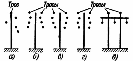
Rice. 1. Arrangement of wires on supports
Reverse tree wire arrangement (Figure 1, c) is preferable to straight tree (Figure 1, b) or hexagon (Figure 1, d) due to more convenient wiring conditions.In this case, raising and lowering the upper wire is not difficult, as is the case, for example, with a straight tree.
The horizontal arrangement of wires (Figure 1, e) has the following advantages:
- eliminates wire collision when dropping ice and wire dancing;
- allows the use of lower supports, which in power lines with large distances between the wires significantly reduces the costs of supports, foundations, transport and installation of supports;
- structurally, it is most convenient for wooden supports;
- reduces the influence of atmospheric waves.
In overhead lines of local networks of class III, that is, with a voltage of up to 1000 V, it is allowed to use any arrangement of wires, regardless of the zone of climatic conditions. In overhead power lines with a voltage above 1000 V, the choice of the location of the wires is mainly influenced by the ice in the area.
On Class I and II overhead lines, in regions with little ice (regions I and II), any arrangement of conductors may be used. In areas with heavy ice (Zones III and IV), horizontal arrangement of wires is recommended.
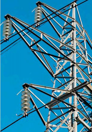
Wires are attached to insulators of overhead power lines using special clamps. For more details on their design and usage features, see here: Clamps for attaching wires to supports
In all the options shown in Figure 1, except the first, there is an asymmetric arrangement of the wires of each circuit relative to each other, as a result of which the inductive resistances of the wires are not the same. Therefore, the voltage drop in the individual conductors is also not the same, even with a uniform phase load, which necessitates the use of such lines rearrangement of the phases (transposition), that is, a change in the relative position of the conductors of individual phases.
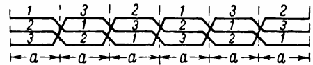
The purpose of reversing the phases is to equalize not only the inductances of the individual wires, but also the capacitances between the wires, as well as to reduce the mutual influence between the individual adjacent parallel circuits. Therefore, the number of permutations per row must be at least three. Depending on the length of the line, the latter is divided into a multiple of three parts, i.e. 3, 6, 9, etc.
For every three sections, one full cycle of permutations is carried out and until the beginning of the next section the wires are in the same places.
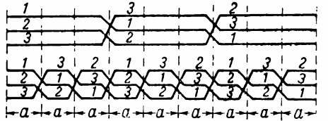
In fig. 2 shows a diagram of two permutation cycles on a three-phase line as an example, and in FIG. 3 is a permutation diagram of a dual three-phase line.
Rice. 2. Rearrange the wires in one row
Rice. 3. Rearranging the twin wires
When two parallel circuits are located, even on one support. Mutually (the influence of the schemes is very small and therefore in practical calculations it is neglected. Note that the need to rearrange the phases usually appears only in lines of 35 kV and above. In lines of local networks with a voltage of up to 10 kV the resulting asymmetry turns out to be insignificant and permutations in such networks, as a rule, are not used.