Voltage and current dividers
Voltage divider
In electrical engineering, voltage dividers are very often used, the operation of which can be checked by applying the voltage distribution rule. The figure shows voltage divider circuits used to step down a given supply voltage (eg 4, 6, 12 or 220 V) to any lower voltage.
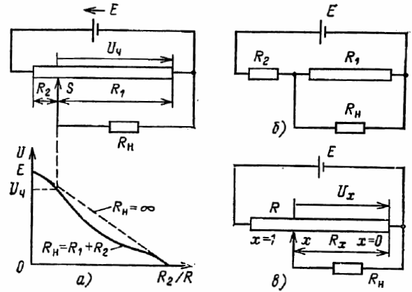
Rice. 1. Voltage divider circuits
In electrical electrical devices, as well as during measurements, it is sometimes necessary to obtain several voltages of a certain value from one source. Voltage dividers are often (and especially in low-current technology) called potentiometers.
The variable partial voltage is obtained by moving the sliding contact of a rheostat or other type of resistor. The constant value partial voltage can be obtained by pushing the resistor or it can be listened to from the junction of two separate resistors.
With the help of the sliding contact, the partial voltage required for the receiver with a resistance (load resistance) can be smoothly changed, while the sliding contact provides parallel connection of the resistances from which the partial voltage is removed.
Resistors are used as part of the voltage divider to obtain a fixed voltage value. In this case, the output voltage Uout is connected to the input Uin (excluding the possible load resistance) through the following connection:
Uout = Uin x (R2 / R1 + R2)
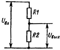
Rice. 2. Voltage divider
An example. Using a resistor divider, you need to get a voltage of 1 V into a 100 kOhm load from a 5 V DC source. The required voltage division ratio is 1/5 = 0.2. We use a separator whose diagram is shown in fig. 2.
The resistance of resistors R1 and R2 should be significantly less than 100 kΩ. In this case, when calculating the divider, the load resistance can be neglected.
Therefore, R2 / (R1 + R2) R2 = 0.2
R2 = 0.2R1 + 0.2R2.
R1 = 4R2
Therefore, you can choose R2 = 1 kOhm, R1 — 4 kOhm. Resistance R1 is obtained by series connection of standard resistors 1.8 and 2.2 kOhm, made on the basis of a metal film with an accuracy of ± 1% (power 0.25 W).
It should be remembered that the divider itself consumes current from the primary source (in this case 1 mA) and this current will increase as the resistance of the divider resistors decreases.
High accuracy resistors must be used to obtain the specified voltage value.
The disadvantage of a simple resistor voltage divider is that with a change in load resistance, the output voltage (Uout) of the divider changes. To reduce the influence of the load on U, you should choose the speed R2 at least 10 times smaller than the minimum load resistance.
It is important to remember that as the resistance of resistors R1 and R2 decreases, the current consumed by the input voltage source increases. Normally, this current should not exceed 1-10 mA.
Current divider
Resistors are also used to direct a given portion of the total current to the corresponding arm of the divider. For example, in the diagram of fig. 3 current Az is part of the total current Azv determined by the resistances of resistors R1 and R2, i.e. we can write that Azout = Azv x (R1 / R2 + R1)
An example. The meter pointer deviates to full scale if the DC current in the moving coil is 1 mA. The active resistance of the coil winding is 100 ohms. Calculate the resistance measuring shunt so that the pointer of the device deviates maximally at an input current of 10 mA (see Fig. 4).
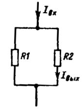
Rice. 3. Current divider
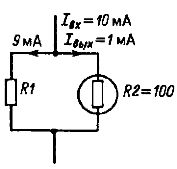
Rice. 4.
The current split ratio is given by the ratio:
Iout / Iout = 1/10 = 0.1 = R1 / R2 + R1, R2 = 100 Ohms
Therefore,
0.1R1 + 0.1R2 = R1
0.1R1 + 10 = R1
R1 = 10/0.9 = 11.1 ohms
The required resistance of the resistor R1 can be obtained by connecting in series two standard thick film resistors of 9.1 and 2 ohms with an accuracy of ± 2% (0.25 W). Note again that in Fig. 3 resistance R2 is internal resistance of the measuring device.
High accuracy (± 1%) resistors should be used to ensure good accuracy in dividing the currents.