Electric capacitors
Electric capacitors are a means of accumulating electricity in an electric field. Typical applications for electrical capacitors are smoothing filters in power supplies, interstage communication circuits in AC amplifiers, noise filtering on power rails for electronic equipment, etc.
Electrical characteristics of the capacitor are determined by its design and the properties of the materials used.
When choosing a capacitor for a particular device, the following circumstances should be considered:
a) the required value of the capacitance of the capacitor (μF, nF, pF),
b) the working voltage of the capacitor (the maximum value of the voltage at which the capacitor can work for a long time without changing its parameters),
c) the required accuracy (possible dispersion of capacitor capacitance values),
d) temperature coefficient of capacity (dependence of the capacity of the capacitor on the ambient temperature),
e) capacitor stability,
f) the dielectric leakage current of the capacitor at rated voltage and a given temperature.(The dielectric resistance of the capacitor can be specified.)
Table 1 - 3 show the main characteristics of different types of capacitors.
Table 1. Characteristics of ceramic, electrolytic and metallized film capacitors
Capacitor Parameter Capacitor Type Ceramic Electrolytic Based on Metallized Film Capacitor Capacitance Range 2.2 pF to 10 nF 100 nF to 68 μF 1 μF to 16 μF Accuracy (possible scatter of capacitor capacitance values), % ±10 and ±20 -10 and +50 ±20 Operating voltage of capacitors, V 50 — 250 6.3 — 400 250 — 600 Capacitor stability Sufficient Poor Sufficient Ambient temperature range, OS -85 to +85 -40 to +85 -25 to +85
Table 2. Characteristics of mica capacitors and capacitors based on polyester and polypropylene
Capacitor Parameter Capacitor Type Mica Polyester Based Polypropylene Based Capacitor Capacitance Range 2.2 pF to 10 nF 10 nF to 2.2 μF 1 nF to 470 nF Accuracy (possible scatter of capacitor capacitance values), % ±1 ±20 ±20 Operating voltage of capacitors, V 350 250 1000 Capacitor stability Excellent good good Ambient temperature range, OS -40 to +85 -40 to +100 -55 to +100
Table 3. Characteristics of mica capacitors based on polycarbonate, polystyrene and tantalum
Capacitor parameter
Condenser type
Based on polycarbonate
Based on polystyrene
Based on tantalum
Capacitor capacity range 10 nF to 10 μF 10 pF to 10 nF 100 nF to 100 μF Accuracy (possible dispersion of capacitor capacity values), % ±20 ±2.5 ±20 Operating voltage of capacitors, V 63 — 630 160 6.3 — 35 Capacitor Stability Excellent Good Sufficient Ambient Temperature Range, OS -55 to +100 -40 to +70 -55 to +85
Ceramic capacitors are used in decoupling circuits, electrolytic capacitors are also used in decoupling circuits and smoothing filters, and metallized film capacitors are used in high-voltage power supplies.
Mica capacitors used in sound reproduction devices, filters and oscillators. Polyester capacitors are general purpose capacitors and polypropylene capacitors used in DC voltage circuits.
Polycarbonate capacitors are used in filters, oscillators and timing circuits. Polystyrene and tantalum capacitors are also used in synchronization and separation circuits. They are considered general purpose capacitors.
Small notes and tips for working with capacitors
You should always remember that the operating voltages of the capacitors must decrease with increasing ambient temperature, and to ensure high reliability it is necessary to create a large voltage reserve.
If the maximum continuous operating voltage of the capacitor is specified, this refers to the maximum temperature (unless otherwise specified). Therefore, capacitors always operate with a certain margin of safety. however, it is necessary to ensure their real working voltage at the level of 0.5-0.6 of the permitted value.
If the capacitor has a certain AC voltage limit, this refers to a frequency of (50-60) Hz. For higher frequencies or in the case of pulsed signals, the operating voltage must be further reduced to avoid overheating of the devices due to dielectric losses.
Large capacitors with low leakage currents can hold the accumulated charge for quite a long time after the equipment is turned off. To ensure greater safety, a 1 MΩ (0.5 W) resistor should be connected in parallel to the capacitor in the discharge circuit.
In high voltage circuits, capacitors are often used in series. To equalize the voltages on them, you need to connect a resistor with a resistance of 220k0m to 1 MΩ in parallel to each capacitor.
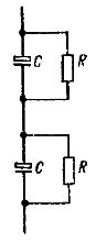
Rice. 1 Using resistors to equalize capacitor voltages
Ceramic pass capacitors can operate at very high frequencies (over 30 MHz)… They are installed directly on the device case or on a metal screen.
Non-polar electrolytic capacitors have a capacity from 1 to 100 μF and are designed for r.m.s. tension 50 V. In addition, they are more expensive than conventional (polar) electrolytic capacitors.
When choosing a capacitor for a power filter, you need to pay attention to the amplitude of the pulse of the charging current, which can significantly exceed the permissible value…. For example, for a capacitor with a capacity of 10,000 μF, this amplitude does not exceed 5 A.
When using an electrolytic capacitor as a decoupling capacitor, it is necessary to correctly determine the polarity of its inclusion... The leakage current of this capacitor can affect the mode of the amplifier stage.
In most applications, electrolytic capacitors are interchangeable... You just need to pay attention to their operating voltage value.
The lead on the outer foil layer of polystyrene capacitors is often marked with a color run. It must be connected to the common point of the circuit.
At high frequencies, the resistance of the parasitic inductances of the capacitor increases, which worsens its characteristics. Figure 2 shows a simplified capacitor equivalent circuit, taking into account the inductance of the inputs.
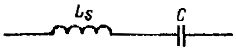
Rice.2 Equivalent circuit of a high-frequency electric capacitor
Capacitor color coding
In the case of most capacitors, their nominal capacity and operating voltage are listed. However, there is also color coding.
Some capacitors are marked with a two-line inscription. The first row shows their capacity (pF or μF) and accuracy (K = 10%, M — 20%). The second row shows the allowable DC voltage and dielectric material code.
Monolithic ceramic capacitors are marked with a three-digit code. The third digit indicates how many zeros must be signed to the first two to obtain the capacity in picofarads.
A color code that indicates the rating of a capacitor (288kb)
An example. What does capacitor code 103 mean? Code 103 means that you need to assign three zeros to the number 10, then you get the capacitance of the capacitor — 10,000 pF.
An example. The capacitor is labeled 0.22 / 20 250. This means that the capacitor has a capacitance of 0.22 μF ± 20% and is designed for a constant voltage of 250 V.