The simplest calculation of power transformers and autotransformers
Sometimes you have to make your own power transformer for the rectifier. In this case, the simplest calculation of power transformers with a power of up to 100-200 W is carried out as follows.
Knowing the voltage and the highest current that the secondary winding must deliver (U2 and I2), we find the power of the secondary circuit: In the presence of several secondary windings, the power is calculated by adding the powers of the individual windings.

Also, taking the efficiency of a low-power transformer equal to about 80%, we determine the primary power:
Power is transferred from the primary to the secondary through the magnetic flux in the core. Therefore, the power value P1 depends on the cross-sectional area of the core S, which increases with increasing power. For a core made of normal transformer steel, S can be calculated using the formula:

where s is in square centimeters and P1 is in watts.
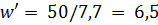
The value of S determines the number of turns w' per volt. When using transformer steel

If you need to make a core of lower quality steel, for example, from tin, roofing iron, steel or iron wire (they must be preheated to become soft), then S and w' must be increased by 20- 30%
Now you can calculate the number of turns of the coils


etc.
In load mode, there may be a noticeable loss of some of the voltage in the resistance of the secondary windings. Therefore, it is recommended that they take the number of turns by 5-10% more than calculated.
Primary current

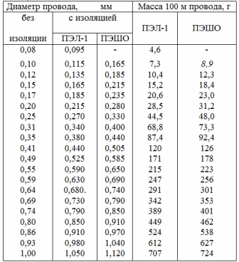
The diameters of the winding wires are determined by the values of the currents and are based on the permissible current density, which for transformers is taken as an average of 2 A / mm2. At such a current density, the diameter of the wire without insulation of each winding in millimeters is determined from the table. 1 or calculated by the formula:

When there is no wire of the required diameter, then several thinner wires connected in parallel can be taken. Their total cross-sectional area must be at least that which corresponds to the calculated single conductor. The cross-sectional area of the wire is determined according to the table. 1 or calculated by the formula:

For low-voltage windings that have a small number of turns of thick wire and are located on top of other windings, the current density can be increased to 2.5 or even 3 A / mm2, since these windings have better cooling. Then, in the formula for the diameter of the wire, the constant factor instead of 0.8 should be 0.7 or 0.65, respectively.
Finally, check the placement of the coils in the main window.The total cross-sectional area of the turns of each winding is (by multiplying the number of turns w by the cross-sectional area of the wire equal to 0.8d2 from, where dfrom is the diameter of the wire in the insulation . This can be determined from table 1, which also shows the mass of the conductor. The cross-sectional areas of all the windings are added. To take into account approximately the looseness of the winding, the effect of the frame of the insulating seals between the windings and their layers, it is necessary to increase the area found by 2- 3 times The area of the core window should not be less than the value obtained from the calculation.
table 1
As an example, let's calculate a power transformer for a rectifier feeding some vacuum tube device. Let the transformer have a high-voltage winding designed for a voltage of 600 V and a current of 50 mA, as well as a winding for heating lamps, with U = 6.3 V and I = 3 A. Mains voltage 220 V.
Determine the total power of the secondary windings:

Primary power
Find the cross-sectional area of the steel core of the transformer:
Number of turns per volt
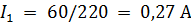
Primary current
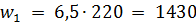
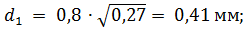
The number of turns and the diameter of the wires of the coils are equal:
• for primary winding
• to increase winding


• for winding incandescent lamps

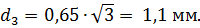
Assume that the core window has a cross-sectional area of 5×3 = 15 cm2 or 1500 mm2, and the diameters of the selected insulated conductors are as follows: d1iz = 0.44 mm; d2iz = 0.2 mm; d3out = 1.2 mm.
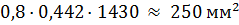
Let's check the placement of the coils in the main window. We find the cross-sectional area of the windings:
• for primary winding
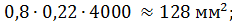
• to increase winding
• for winding incandescent lamps
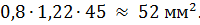
The total cross-sectional area of the windings is approximately 430 mm2.
As you can see, it is more than three times the area of the window, and therefore the coils will fit.
The calculation of the autotransformer has some peculiarities. Its core should be counted not for the total secondary power P2, but only for that part of it that is transmitted by the magnetic flux and can be called the transforming power RT.
This power is determined by the formulas:
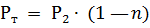
— for a step-up autotransformer
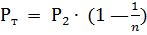
— for the step-down autotransformer and

If the autotransformer has taps and will work at different values of n, then in the calculation it is necessary to take the value of n that is most different from unity, since in this case the value of Pt will be the largest and it is necessary core to be able to transmit such power.
Then the calculated power P is determined, which can be taken as 1.15 • RT. The factor 1.15 here accounts for the efficiency of the autotransformer, which is usually slightly higher than that of the transformer. e
In addition, the formulas for calculating the cross-sectional area of the core (in relation to the power P), the number of turns per volt, the above-mentioned wire diameters for the transformer are applied. It should be noted that in the part of the winding that is common to the primary and secondary circuits, the current is equal to I1 — I2 if the autotransformer is increasing, and I2 — I1 if it is decreasing.