The use of the energy of the water flow, the device of hydraulic structures of hydroelectric power plants (HPP)
Energy of water flows
The energy (potential) that the water flow has is determined by two quantities: the amount of flowing water and the height of its fall to the mouth.
In a natural state, the energy of the river flow is spent on erosion of the channel, transfer of soil particles, friction on the banks and the bottom.
In this way, the energy of the water flow is distributed throughout the flow, albeit unevenly — depending on the slopes of the bottom and the secondary flow rate of the water. In order to use the energy of the flow within a certain area, it is necessary to concentrate it in one section - in one alignment.
Sometimes such a concentration is created by nature in the form of waterfalls, but in most cases it must be created artificially, with the help of hydraulic structures.
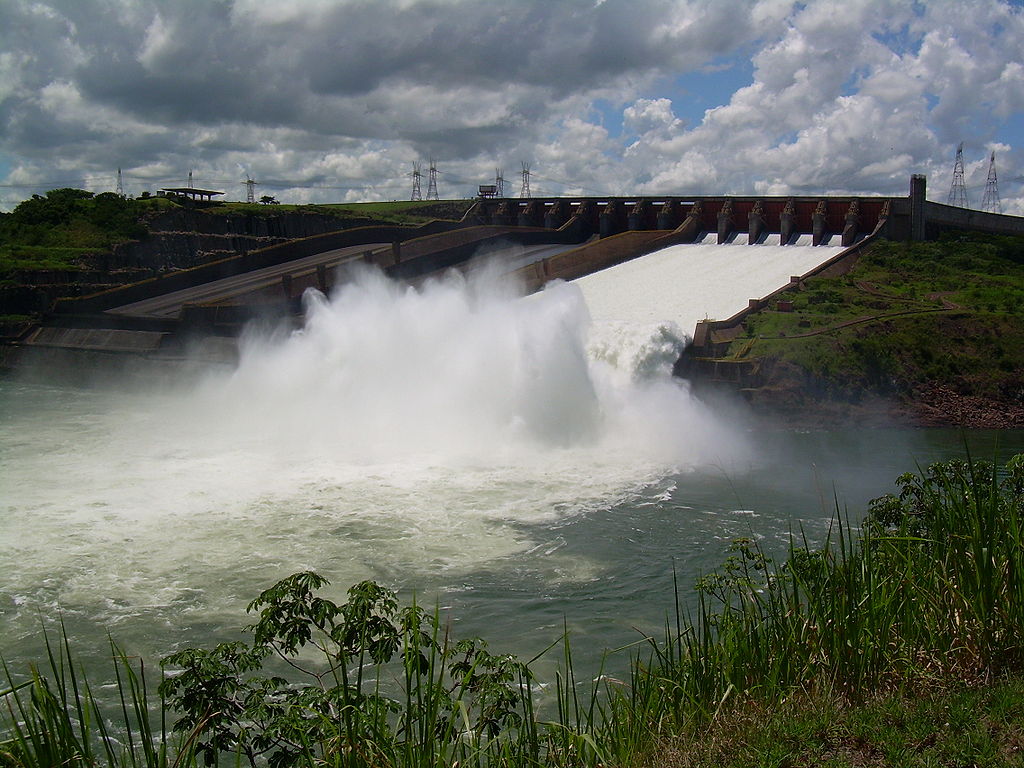
The Itaipu Hydroelectric Plant is the largest hydroelectric power plant in the world for the production of electricity
Energy is concentrated at the construction site hydroelectric power plants (HPP) two ways:
-
a dam blocking the river and raising water in the basin upstream — upstream N meters from the level of the basin downstream — downstream. The difference in upstream and downstream levels H is called head. Hydroelectric plants where the head is created by a dam are called near-dam and are usually built on flat rivers;
-
with the help of a special bypass channel — a derivation channel. Derivation stations are mainly built in mountainous areas. The diversion canal has a very small slope, so at its end the entire head of the river section surrounded by the canal is almost completely concentrated.
Flow force in structure alignment is determined by the amount of water passing through the gate in one second, Q and head H. If Q is measured in m3/sec, and H in meters, then the flow rate in the section will be equal to:
Pp = 9.81 * Q* 3 kW.
Only a part of this capacity, equal to the efficiency of the installation, will be used in the electric generators of the hydroelectric plant. Therefore, the power of the power plant at head H and water flow through the turbines Q will be:
P = 9.81*B* H* efficiency kW.
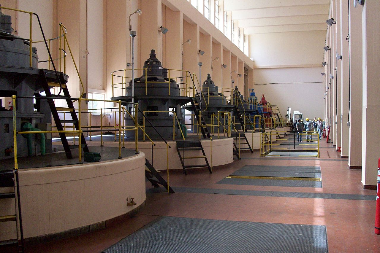
Engine room for a hydroelectric plant
In real operating conditions of hydroelectric plants, some of the water may be discharged past the turbines.
The energy of streams has been used for centuries. The widespread use of water power became possible only at the end of the 19th century, when it was invented electrical transformer and created three-phase alternating current system... The ability to transmit energy over long distances made it possible to harness the energy of the most powerful water currents.
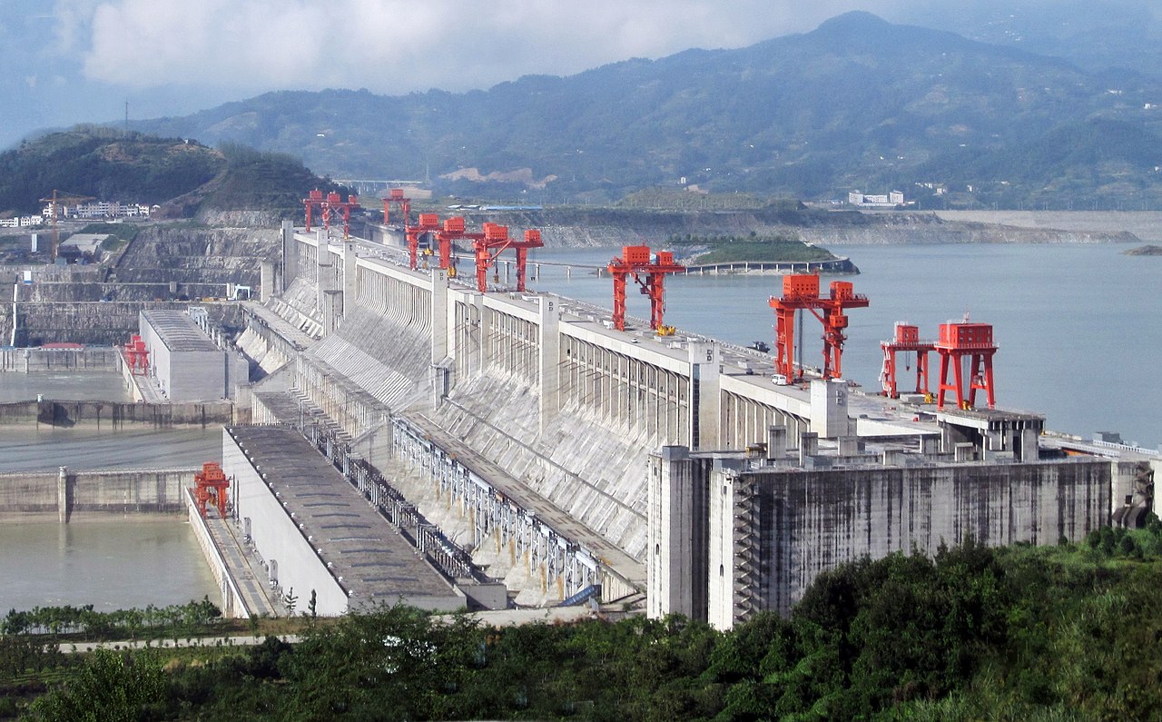
China's Three Gorges Hydroelectric Plant, located on the Yangtze River, is the largest in the world in terms of installed capacity.
Composition and arrangement of hydrotechnical facilities of hydroelectric power plants
The structure of the unit of structures of a dam hydroelectric power plant usually includes:
-
dam head. In the upper reaches of the dam, a reservoir with a larger or smaller volume is formed depending on the topographical conditions and the height of the dam, which regulates the flow of water through the turbines in accordance with the load schedule;
-
hydroelectric building;
-
gutters, having a different purpose and correspondingly different design: to discharge the excess water that is not used in the turbines, for example during floods (overflows); for lowering the water horizon in the overflow waters, which is sometimes necessary, for example, when repairing hydraulic facilities (drainage); for distribution of water between water users (water intake facilities);
-
transport facilities — navigable locks, providing by navigation on the river, shelves and rafts for wooden rafting;
-
fish passage facilities.
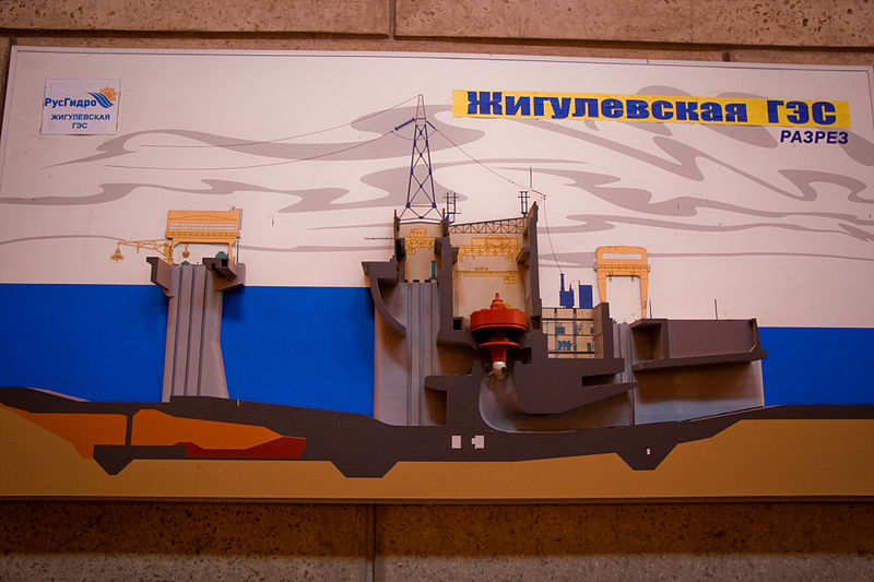
Section on the building of the hydroelectric plant
Typical structures of the derivation hydroelectric plant — diversion channel and piping from the channel to the turbines.
The main value, the most technically responsible and the most expensive link in the block of hydropower plants is the dam. Dams are distinguished along the path of water passage:
-
deafwhich do not allow the passage of water;
-
spillwayin which the water overflows over the crest of the dam;
-
panel boardwhich let water in when the shields (gates) are opened.
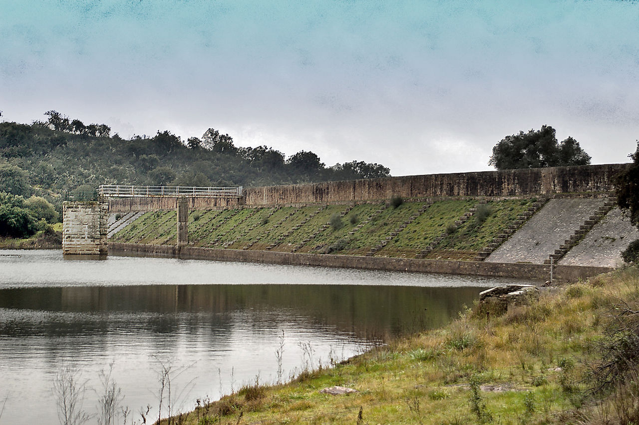
Cornalvo is a dam in Spain, in the province of Badajoz, that has been in operation for almost 2,000 years.
Dams are usually earthen and concrete.

The transverse profile of the earth dam: 1 — tooth; 2 — protective layer of sand and gravel; 3 — clay grid: 4 — dam body; 5 — waterproof base layer
The figure shows the profile of a clay dam built on a permeable layer of low thickness. The body of the dam is discharged from any soil that does not contain a large amount of organic impurities and water-soluble salts.
When filling a dam with permeable soils, a clay grid is placed in the body of the dam to prevent water filtration. The permeable layer on which the dam is built is cut by a waterproof tooth for the same reasons.
If the dam is completely filled with clay or sandy soil, then there is no need for a seepage barrier. On top, the screen is covered with a protective layer of sand and gravel, which in turn is protected from wave erosion by a stone pavement (from the crest of the dam to a mark that lies 0.5 — 0.7 m below the lowest possible water horizon in the upper waters).
When filling a clay dam, each layer is carefully compacted with rollers. Draining water through the crest of a clay dam is inadmissible, as there is a danger of its erosion. A road is usually built along the crest of an earthen dam, which defines the width of the crest. The ridge is asphalted in the usual way.
The width of the base of the dam depends on its height and on the assumed inclination of the slopes to the horizon. The upstream slope becomes flatter than the downstream slope.
Currently, the hydromechanization method is widely used in the construction of large earthen dams.
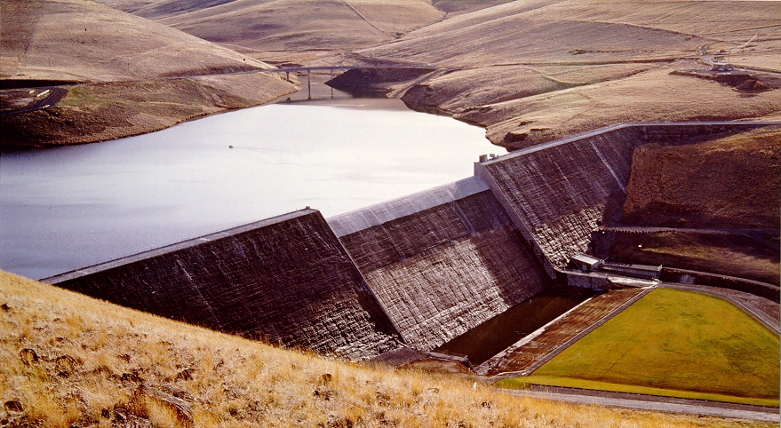
Willow Creek Dam, Oregon, USA, a gravity-type dam made of concrete

Scheme of a blind concrete dam: 1 — drainage of the dam; 2 — viewing gallery; 3 — collector; 4 — drainage of the base
The figure shows an empty concrete dam with a regular profile with a traffic lane on top. For a more reliable connection of the dam with the soil and banks, the foundation of the dam is made in the form of several ledges. A tooth with a depth of 0.05 — 1.0 Z is located on the pressure side.
To combat filtration, anti-filtration curtains are placed under the tooth, for which, through a system of boreholes with a diameter of 5 — 15 cm, the cement solution is injected into the cracks of the base (soil).
Although the body of the dam is made of solid concrete, water always seeps through it. In order to drain this water downstream, a drainage system is arranged in the dam, consisting of vertical wells - drains (with a diameter of 20 - 30 cm) made in the body of the dam every 1.5 - 3 m.
The water drained through them enters the cuvettes of the observation gallery 2, from where it is led through horizontal collectors 3 to the lower pool. The observation gallery, which runs in the body of the dam along its entire length, is made to monitor the condition of concrete and water filtration.
Derived water supply structures are most often implemented in the form of an open channel. In soft soils, the channel section is usually trapezoidal. The walls and bottom of the channel are lined with concrete or asphalt to reduce filtration, prevent erosion, reduce roughness and associated pressure losses. Cobblestone cladding is also used.
Diversion channels in rocky soils have a rectangular section. If it is not possible to carry out an open channel, recesses with a rectangular or circular cross-section are used. Water from the diversion channel to the turbines is fed through pipelines. The pipelines are metal, reinforced concrete and wooden.