Electrical equipment of metal cutting machines
Among the various methods of producing a product with a complex shape in modern engineering, metal cutting takes first place. Metal cutting machines, together with forging and casting machines, are the type of equipment that underlies the production of all modern machines, tools, instruments and other products for industry, agriculture and transport.
Mechanical machines are machines for making the machines themselves. The technical culture and progress of mechanical engineering depend mainly on mechanical engineering. Metal cutting machines are distinguished by a very wide variety in terms of purpose, device, dimensions, forms of execution and accuracy.
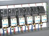
The electrical equipment of metal cutting machines includes electric motors (asynchronous squirrel-cage motors, DC motors), electromagnets, electromagnetic clutches, travel and limit switches, various sensors (for example, oil pressure control in the hydraulic system), control buttons, switches, signal lamps , magnetic starters, relays, transformers that reduce the voltage to the control circuit, alarm circuit and local lighting, protective devices (circuit breakers, fuses and thermal relays).
The electrical equipment and automation of modern metal cutting machines include various programmable controllers, frequency converters, soft starters for electric motors, non-contact starters, non-contact limit switches and other electronic and programmable controls.
The electrical equipment of metal cutting machines is located on the machine itself, on the control panel and in the control cabinet, which is usually located next to the machine.
This article discusses what are the characteristics and differences of the electrical equipment of various most common metal cutting machines: turning, drilling, milling, grinding and planing.
The main types of metal cutting machines
Mechanical processing of metal-cutting machines is aimed at such a change in the workpiece by removing chips from it, after which the workpiece will take a shape close to the required (rough and preliminary processing) or coincide with it with a certain accuracy geometric shape, dimensions (finishing) and the surface finish (fine tuning).Depending on various factors, the necessary change of the shape of the part is carried out using different types of processing and on different machines.
Currently, a large number of metal cutting machines are produced, different in purpose, technological capabilities and sizes.
According to the degree of automation, I distinguish:
-
mechanized;
-
automated machines (automatic and semi-automatic machines).
A mechanized machine has one automated operation, such as clamping a workpiece or feeding a tool.
A machine, performing processing, produces all working and auxiliary movements of the technological operation cycle and repeats them without the participation of the worker, who only observes the operation of the machine, controls the quality of processing and, if necessary, adjusts the machine, that is, adjusts it to restore the accuracy achieved during the adjustment of the relative position of the tool and the workpiece, the quality of the workpiece.
A cycle is understood as a period of time from the beginning to the end of a periodically repeated technological operation, regardless of the number of simultaneously produced parts.
Semi-automatic device - a machine that operates in an automatic cycle, the repetition of which requires the intervention of the worker. For example, the worker must remove a part and set a new part, then turn on the machine for automatic operation in the next cycle.
Main (working) movements of the machine divided into main (cutting) movement and feed movement... The main movement and feed movement can be rotational and rectilinear (translational), they are performed by both the workpiece and the tool.
Auxiliary movements include movements for setting, tightening, loosening, lubrication, chip removal, tool dressing, etc.
Machining products on machine tools gives the workpiece the required surface shape and dimensions by moving the cutting edge of the tool relative to the workpiece or the workpiece relative to the cutting edge of the tool. The required relative motion is created by a combination of tool and workpiece motions.
In fig. 1. shows diagrams of typical types of processing performed on metal-cutting machines, which include: turning (Fig. 1, a), planing (Fig. 1, b), milling (Fig. 1, c), drilling (oriz. 1, d) and grinding (Fig. 1, e).
When turning on lathes, carousels, face and other machines, the main movement 1 is rotational, performed by workpiece 3, and the feed movement 2 is translational, performed with tool 4 (mill).
When planing on planing machines, the main movement 1 and the feed movement 2 are translational. In longitudinal planing, the main movement is carried out by workpiece 3, and the feed movement is by cutter 4, and in transverse planing, the main movement is carried out by cutter 4, and the feed is carried out by workpiece 3.
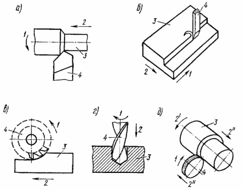
Rice. 1. Typical types of machine tool processing products
When milling, the main movement 1 is rotational, it is carried out by the tool - cutter 4, and the feeding movement 2 is translational, it is carried out by the workpiece 3.
When drilling drilling machines, the main movement 1 is rotational, and the feed movement 2 is translational, both movements are carried out by the tool - drill 4. The workpiece 3 is stationary.
When grinding grinding machines, the main movement 1 is rotational, it is carried out by the tool - grinding disc 4, and the feed movement of two types is rotational 2 ', it is carried out by workpiece 3 and progressive 2 «, it is carried out by grinding 4 or detail 3.
Modern metal cutting machines have individual (from a separate source of motion) drives. The source of motion in metal cutting machines is usually an electric motor. The electric motor can be located next to the machine, inside it, on the machine, it can be built into the headstock, etc.
In the machining process of a metal cutting machine, it is necessary to maintain the set cutting speed and the selected feed. Deviation from the selected cutting mode causes a deterioration in the quality of processing or a decrease in productivity. Therefore, the electric drive of the machine must maintain an approximately constant speed with changes in load caused by fluctuations in allowance (except for some types of control). This requirement is met by electric motors with fairly rigid mechanical characteristics.
For any metal cutting machine, the electric motor and the kinematic chain of the machine together provide the necessary cutting speed. In most special machines, the spindle frequency (speed) is unchanged.
The gearbox drive is currently the most common type of main drive in metal cutting machines. Their advantages are compactness, ease of operation and reliability in operation.
The disadvantages of gearbox drives are the inability to smoothly adjust the speed, as well as relatively low efficiency at high speeds in the case of a wide control range.
The following methods are used in the machines for stepless adjustment of the speeds of the main movement and the feed movement:
1. Electrical regulation is performed by changing the speed of the electric motor that drives the corresponding circuit of the machine.
2. Hydraulic regulation is mainly used to control the speed of rectilinear movements (when planing, cutting, stretching), much less often — rotary movements).
3. Adjustment using mechanical variators. Most mechanical variators used in machine tools are friction variators.
A CVT is a mechanism for smoothly and smoothly adjusting the transmission ratio between the drive and the drive.
See also: Electric drives for CNC machine tools
Electrical equipment of lathes
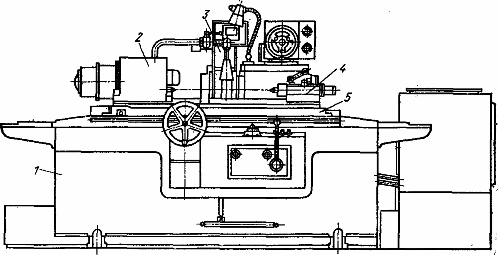
The general view of the lathe is shown in fig. 2. On the bed 1, the head plate 2 is firmly fixed, designed to rotate the product. On the guides of the bed there is a support 3 and a tail 4. The support ensures the movement of the cutter along the axis of the product. In the back, there is a fixed center for holding a long product or a tool in the form of drills, taps, unfolders.
Turning cutters are the most common tool and are used for machining planes, cylindrical and shaped surfaces, threads, etc.

Rice. 2. General view of the lathe
The main types of turning work are shown in the figure. 3.
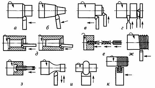
Rice. 3.The main types of turning (arrows show the directions of movement of the tool and rotation of the workpiece): a — processing of the external cylindrical surfaces; b — processing of the external conical surfaces; c — processing of ends and sills; d — turning grooves and grooves, cutting a piece of workpiece; d — processing of internal cylindrical and conical surfaces; e — drilling, sinking and expanding holes; g — cutting an external thread; h — internal thread cutting; and — treatment of shaped surfaces; k — corrugation rolling.
The characteristic features of lathes are the rotation of the product, which is the main movement, and the translational movement of the cutter 2, which is the movement of the feed. The feed can be longitudinal if the cutter moves along the axis of the product (longitudinal rotation), and transverse if the cutter moves along the end surface perpendicular to the axis of the product (transverse rotation).
The disadvantage of the mechanical method of adjusting the speed of the spindle, carried out by switching the gears of the gearbox, is the inability to provide an economically advantageous cutting speed for all diameters of the workpiece, while the machine cannot provide full performance at all speeds.
Figure 4 shows the lathe structure.
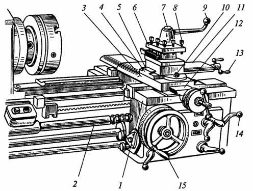
Rice. 4. The device of the lathe carrier: 1 — lower slide (longitudinal support); 2 — leading screw; 3 — transverse sliding of the support; 4 — rotating plate; 5 — drivers; 6 — holder for tools; 7 — rotating head of the tool holder: 8 — screw for fixing the cutters; 9 — a handle for turning the tool holder; 10 — nut; 11 — upper slider (longitudinal support); 12 — guides; 13 and 14 — handles; 15 — handle for longitudinal movement of the support.
Screw lathe designed for different jobs. On them you can:
-
grinding of external cylindrical, conical and shaped surfaces;
-
cylindrical and conical holes;
-
handle end surfaces;
-
cut outer and inner threads;
-
drilling, countersinking and reaming; cutting, trimming and similar operations.
Turret lathes used in batch production to machine complex configuration parts from bars or billets.
Vertical turning lathes are used to process heavy parts with a large diameter but relatively short length. They can be used for grinding and drilling cylindrical and conical surfaces, cutting ends, cutting annular grooves, drilling, countersinking, flaring, etc.
Basic drives of lathes and drilling machines for a wide range of applications, small and medium, the main type of drive is an induction squirrel-cage motor.
The asynchronous motor is structurally well combined with the gearbox of the machine tool, it is reliable in operation and does not require special maintenance.
Lathes for heavy duty and vertical lathes generally have an electromechanical stepless speed control of the main drive using a DC motor.
Stepless electrical speed control (two-zone) is used in the automation of machines with a complex duty cycle, which makes it easy to readjust them to any cutting speed (for example, some automatic lathes for lathes).
Drive device Small and medium-sized lathes are most often driven by the main motor, which provides the ability to cut threads. To adjust the feed rate, multi-stage feed boxes are used.Gears are shifted manually or using electromagnetic friction clutches (remotely).
Some modern lathes and boring machines use a separate DC drive with wide control for the feeder. In modern metal cutting machines — asynchronous drive with variable frequency.
Auxiliaries are used for: coolant pump, quick caliper movement, tail movement, tail clamping, quill movement, gearbox gear movement, lubrication pump, motor control rheostat movement, part clamping, stable movement rest, rotation of the spindles of movable devices (milling, grinding, etc.). Most of these drives are only available on heavy metal cutting machines.
Additional electromechanical devices: electromagnetic clutches to control the feed of the slide, electromagnetic clutches to switch the revolutions of the spindle.
Automation elements: motor stop during machine interruptions, automatic retraction of the cutter at the end of processing, programmed digital control and cycle control, electric copying.
Control and signaling: tachometers, ammeters and wattmeters in the main circuit of the drive motor, tools for determining the cutting speed, bearing temperature control, lubrication control.
Recently, software control of lathes has developed very rapidly. Along with a large number of computer-controlled lathes, multi-operation machines are produced for universal multi-tool machining of a wide range of parts.
Multipurpose machines are programmed and equipped with an automated tool shop. The tool change is programmed and performed automatically between the individual processing stages.
When processing rotating bodies with a complex shape - conical, stepped or with curved formers - on lathes, the principle of copying is widely used... Its essence lies in the fact that the required profile of the product is reproduced according to a specially prepared template (copier) or per pre-processed part. In the process of copying, a copying finger moves along the contour of the pattern, which has the same shape as the cutter. The movements of the tracking pin are automatically transmitted through the control system to the support with the cutter so that the trajectory of the cutter follows the trajectory of the trajectory of the tracking finger.
Machining parts on copiers can significantly increase the reproducibility (repeatability) of parts in shape and size and labor productivity compared to machining on manual universal machines, because there is no time spent turning the tool holder, cutting and outside the milling cutter for measurements etc. …
However, copier-based automation is complicated by the time-consuming pre-production of copiers and templates. While processing a product and changing patterns takes little time, making a pattern, which is usually done by labor-intensive manual operations, takes a long time (sometimes several months).
See also on this topic: Electrical equipment of lathes
Electrical equipment for drilling machines
Drilling machines designed for through or blind holes, for finishing holes by countersinking and reaming, for cutting internal threads, for countersinking end surfaces and holes.
-
Drilling — the main method of processing holes in a dense material of parts. Drilled holes, as a rule, do not have an absolutely correct cylindrical shape. Their cross-section has the shape of an oval, and the longitudinal section has a slight narrowing.
-
Sensor — is the processing of pre-drilled holes or holes made by casting and stamping to obtain a more accurate shape and diameter than drilling.
-
Reaming — This is the final treatment of drilled and countersunk holes to produce precise cylindrical holes in shape and diameter with low roughness.
There are the following types of universal drilling machines:
-
bench drilling;
-
vertical drilling (single spindle);
-
radial drilling; multispindle;
-
for deep drilling.
Figure 5 shows a general view of a radial drilling machine.
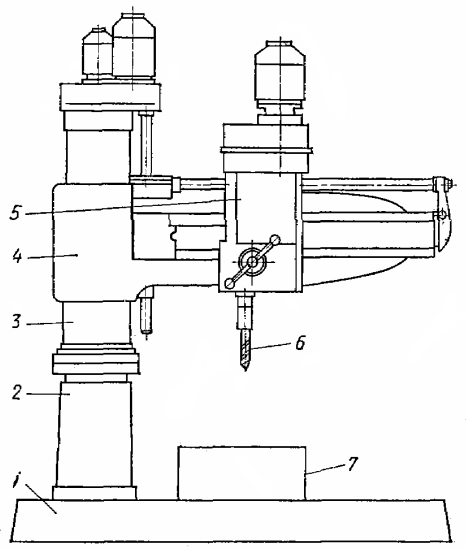
Rice. 5. General view of the radial drilling machine
The radial drilling machine consists of a base plate 1, on which there is a column 2 with a rotating sleeve 3, which rotates 360O... Traverse 4 moves along the sleeve in a vertical direction, along which the spindle head (drilling head) 5 with an electric drive , located on it with speed reducers and the spindle feed moves in a horizontal direction.
When drilling, the product 7 is fixed on a stationary bed table. Drill 6 rotates and moves up and down, all the while penetrating deep into the product. The drive to rotate the planter is the main drive and the drive is the feeder.
The machine control scheme provides interlocks that limit the movement of the crosshead in extreme positions, prohibit operation with an unprotected column and include the motor for lifting the crosshead when it is fixed on the column.
Main motion: Reversible Squirrel Asynchronous Motor, Reversible Pole-Switch Asynchronous Motor, G-D System with EMU (For Heavy Metal Cutting Machines).
Drive: mechanical from the main drive chain, hydraulic drive.
Assistive devices are used to:
- cooling pump,
-
hydraulic pump,
-
raising and lowering the sleeve (for radial drilling machines),
-
column clamping (for radial drilling machines),
-
support movement (for heavy radial drilling machines),
-
turning bushings (for heavy radial drilling machines),
-
table rotation (for modular machines).
Special electromechanical devices and interlocks:
-
solenoids for hydraulic control,
-
cycle automation using way switches,
-
automatic table fixing control,
-
automatic setting of coordinates by program control (for coordinate drilling machines and coordinate tables).
Boring machines are divided into:
-
horizontal drilling;
-
jig boring;
-
diamond drilling;
-
deeply boring machines.
The following works can be performed on horizontal drilling machines:
-
drilling;
-
boring holes;
-
trimming the ends;
-
carving;
-
plane milling.
The main drive of a drilling machine is provided by asynchronous squirrel-cage motors. The speed of the spindle is controlled by shifting the gears of the gearbox.
Heavy duty horizontal drilling machines are driven by DC motors with two or three speed gearboxes.
The feed drive of drilling machines is usually provided by the main motor, for which the feed box is located on the spindle head.
For universal and heavy drilling machines, a DC motor feeder is used according to the GD system (for lighter machines, the PMU-D or EMU-D system is used) or TP-D (for new machines).
Auxiliary devices are used for: cooling pump, rapid movement of the drilling spindle, lubrication pump, switching gears of the gearbox, movement and tensioning of the rack, movement of the adjusting slide of the rheostat.
Special electromechanical devices and interlocks: automation of the control of the main drive when switching gears of the gearbox, devices for illumination of microscopes, devices for reading coordinates with an inductive converter. Modern boring machines are made largely electrified.
More details on the electrical equipment of a CNC drilling machine on the example of the 2R135F2 model: Electrical equipment CNC drilling machine
Electrical equipment of grinding machines
Grinding machines They are mainly used to reduce the roughness of the parts and obtain accurate dimensions.
During grinding, the main cutting movement is performed by an abrasive tool - a grinding disc. It is only rotating and its speed is measured in m/s. Feed movements can be different, they are communicated to the workpiece or tool. Grinding wheels consist of bonded abrasive grains with cutting edges.
Grinding machines, depending on the purpose, are divided into:
- circular grinding;
- internal grinding;
- centerless grinding;
- surface grinding;
- special.
Figure 6 shows the processing scheme of surface grinding machines with the designation of movements, in Figure 7 - schemes of circular external grinding, and Figure 8 - a general view of the circular grinding machine.
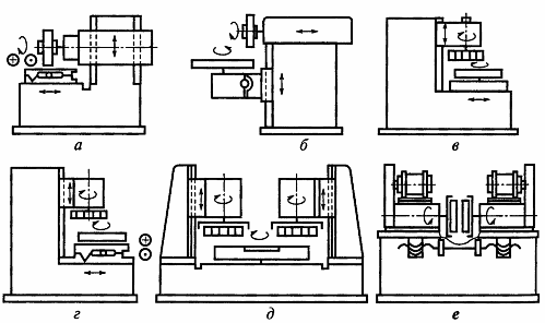
Rice. 6. Processing scheme of surface grinding machines with designation of movements: a — b — with horizontal spindles working on the periphery of the grinding disk (a — with a rectangular table; b — with a round table); c — d — with vertical spindles, single-spindle, working with the back end of the grinding disc (c — with a round table; d — with a rectangular table); e — f — two-spindle machines working with the front side of the grinding disc (d — with two vertical spindles; f — with two horizontal spindles).
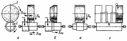
Rice. 7. Schemes of circular external grinding: a — grinding with longitudinal working strokes: 1 — grinding disk; 2 — grinding detail; b — deep grinding; c — grinding with deep cutting; d — combined grinding; Spp — longitudinal feed; Sp — cross feed; 1 — processing depth.
Rice. 8. General view of the cylindrical grinding machine
The circular grinding machine (Fig. 8) consists of the following main units: bed 1, grinding head 3, excavator 2, tail 4, pillar 5. Grinding machines have a device for dressing the grinding disc (not shown in the figure). The bed and table of the cylindrical grinding machine are shown in the figure.
The lower table 6 is mounted on the longitudinal guides of the bed, on which the rotating upper table 5 is mounted. The table 5 can be rotated with a screw 2 around the axis of the bearing 4.The fixed rotation of the table 5 is necessary for processing cone surfaces. The lower table is moved by a hydraulic cylinder fixed to the bed. A plate is fixed on the bed, on the transverse guides on which the grinding head moves.
Grinding machines are precision machines, so the designs of their individual assemblies and kinematic transmissions must be as simple as possible, which is achieved by the extensive use of individual drive. In grinding machines, the following types of electric drives are distinguished: main drive (rotation of the grinding disc), product rotation drive, driving drive, auxiliary drives and special electromechanical devices.
In small and medium-sized grinding machines with a main drive power of up to 10 kW, the rotation of the wheel is usually carried out by single-speed asynchronous squirrel-cage motors. Cylindrical grinding machines with significant grinding wheel sizes (diameter up to 1000 mm, width up to 700 mm) use gear belt drives from the motor to the spindle and an electric brake on the drive to reduce the stopping time.
On internal grinding machines, processing is carried out in circles of small dimensions, therefore they use accelerating transmissions from the motor to the spindle or use special high-speed asynchronous motors built into the body of the grinding head. A device in which a squirrel-cell motor and a grinding spindle are structurally combined into one unit is called an electrospindle.
main drive... To rotate the workpiece on internal grinding machines, squirrel-cage asynchronous motors, single or multi-speed… In heavy cylindrical grinding machines, the product rotation drive is carried out according to the G-D system and drives with thyristor converters.
Innings (reciprocating movement of the table, longitudinal and transverse movement of the grinding head) of small grinding machines is carried out by a hydraulic drive. The driving drives of heavy flat and cylindrical grinding machines are carried out by a direct current motor according to the EMU-D, PMU-D or TP-D system, a variable hydraulic drive is often used.
Auxiliary drives are used for: hydraulic pump with transverse periodic feed, transverse feed (asynchronous squirrel motor or DC motor of heavy metal cutting machines), vertical movement of the grinding wheel head, cooling pump, lubrication pump, conveyor and washing, magnetic filter.
Special electromechanical devices and interlocks: electromagnetic tables and plates; demagnetizers (for demagnetizing parts); magnetic filters for coolant; count the number of cycles to dress the circle; active control device.
Electromagnetic plates and rotating electromagnetic tables are widely used in surface grinding machines for fast and reliable fastening of steel and cast iron workpieces. Permanent magnet clamping plates (magnetic plates) are used on precision grinding machines.
To increase productivity and ensure high accuracy, modern grinding machines of all types are equipped with active control devices — measuring devices for active control of ground parts during their processing and sending appropriate commands to the machine control system .
When the required workpiece size is reached, the machine automatically shuts off. The worker does not stop the machine to check the workpiece dimensions. He just removes the finished part, installs a new part and starts the machine.
The simplest measuring device for automatic control of the dimensions of parts during processing on internal grinding machines is a gauge that is periodically brought to the workpiece.
On surface grinders with continuous part loading, electrocontact measuring devices are used for automatic adjustment of the machine.
Electrical equipment of milling machines
Milling machines process flats, shaped surfaces, grooves, cut external and internal threads, gears and multi-cutting tools with straight and helical teeth (mills, reamers, etc.). Milling cutters-multi-tooth (multi-ended tool). Each cutting tooth is the simplest cutter. A general view of a horizontal milling cutter is shown in figure 9. The main types of milling cutters are shown in figure 10.

Rice. 9. General view of the horizontal milling machine
The cutting tool (miller 4) is mounted on a mandrel 3 fixed in the spindle 5 and a suspension 2 located on the rack 1. The main movement of the machine is the rotation of the cutter, which is rotated by the main drive located inside the bed. The product 6 is mounted on a table 7, moving in the direction of rotation of the cutter along the guides of the rotary plate 8, mounted on a slide 9, moving along the console 10 in a direction perpendicular to the rotation of the cutter. The console itself moves in a vertical direction along the guides of the bed II.
The feed motion of the machine is the motion of the product. Main feed — longitudinal feed of the table in the direction of rotation of the cutter.The table feed device is located inside the console. The machine also provides cross feed for sliders and vertical feed for brackets. The presence of a rotating plate allows the table to be rotated in a horizontal plane and placed at the required angle. In simple milling machines, there is no rotating plate.
Vertical milling cutters are generally built on the same basis as horizontal milling cutters, they have essentially the same design except for the bed, the spindle unit in which it is mounted vertically. There are vertical milling machines where the spindle is mounted in a spindle head that rotates in a vertical plane at a certain angle to the plane of the table. There is no turntable in the feed mechanisms of vertical cutters.
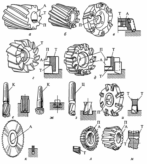
Fig. 10. The main types of cutters: a, b — cylindrical; c, d, e — end; f, g — end; h — key; i- disk two- and three-sided; k — slot and segment; l — angle; m — shaped; A — knives with cylindrical or conical holes; T — end bases for fixing milling cutters; P — cutters with longitudinal and transverse keys; K and Ts — conical and cylindrical end mills
Main drive. Single or multi-speed asynchronous squirrel-cage motors in combination with a gearbox are used to drive the main motion of small and medium-sized milling machines. Engines are usually flanged. The drive of such machines in most cases is carried out by the main engine through a multi-stage feed box.
The main drive of milling machines with heavy layers is also carried out by asynchronous motors with a mechanical change in the angular speed of the spindle.
Drive device.For the drives of the feed tables and milling heads of such machines, DC motors are used, which are switched on according to the G-D system with the EMU as an exciter. Currently, the TP-D system and frequency-controlled asynchronous electric drive are used for such drives.
Auxiliary drives Used for rapid movement of milling heads, movement of cross beam (for longitudinal cutters), clamping of cross bars, cooling pump, lubrication pump, hydraulic pump.
In horizontal milling machines, the flange motors are usually mounted on the back wall of the bed, and in vertical milling machines, they are most often mounted vertically at the top of the bed. The use of a separate electric motor for the feeder greatly simplifies the design of milling machines. This is acceptable when gear cutting is not performed on the machine.
Software cycle control systems are common in milling machines. They are used for rectangular shaping. Numerical control schemes are widely used to process curved contours.
Copy milling cutters are designed for processing spatially complex surfaces by copying models. These machines are used to manufacture hydraulic turbine wheels, forging and punching dies, linear and press dies, etc. The processing of such products on universal machines is practically impossible.
The most widespread are the copier-milling machines with electric tracking - electrocopier cutters.
See also on this topic: Electrical equipment of milling machines
Electrical equipment of planing machines
The group of planing machines includes transverse planers, planers and milling machines.A characteristic feature of planers is the reciprocating movement of the cutter or part with the planing mode during the forward stroke and the execution of an intermittent cross feed after each single or double stroke of the cutter or part.
Cutting machines are used to plan large parts. These machines are available in different sizes with a table length of 1.5 - 12 m.
The general view of the planer is shown in fig. eleven.
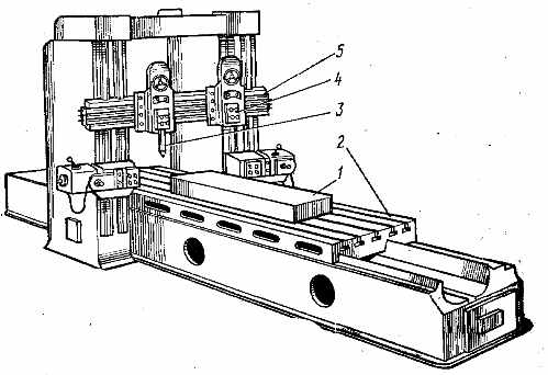
Rice. 11. General view of the grater
In these machines, the workpiece 1 is fixed on the table 2, which performs reciprocating movement, and the milling cutter 3, fixed on the vertical support 4, mounted on the traverse 5, remains stationary. The planing process is carried out with the working stroke of the table forward, and with a reverse stroke the milling cutter is raised. After each return stroke of the table, the cutter moves in a transverse direction, providing a transverse feed.
The longitudinal movement of the table during the working stroke is the main movement, and the movement of the cutter is the feed movement. Auxiliary movements are rapid movements of the crosshead and machine carriages, lifting of the cutter during table retraction, and set-up operations.
Planers have a main drive, cross feed drive and auxiliary drives. The main electric drive of the planer provides reciprocating movements of the workpiece table. The electric drive is reversible. When the table moves forward, the main motor is loaded according to the cutting conditions, and when it moves backward, the motor load is used only to move the table with the part without the planing process.Electric drive provides smooth control of cutting speed.
The main electric drive of the planer provides the technological process of the machine according to the speed schedule of the table. The operation of the main electric drive of the planer is associated with frequent turns with large starting and braking moments. In longitudinal planers, the table is driven by a DC motor powered by thyristor converters.
Caliper feed Planing is done periodically for each stroke of a double table, usually when reversing from reverse to straight, and must be completed before cutting begins. Mechanical, electrical, hydraulic, pneumatic and mixed drive systems are used for the implementation of such a power supply, of which the most widespread are the electromechanical ones, implemented by an AC asynchronous motor with the help of screw or rack and pinion mechanisms.
Auxiliary drives, which ensure the rapid movement of the cross beam and supports, as well as the lifting of the cutters during the return stroke of the table, are performed by asynchronous motors and electromagnets, respectively.
The scheme for automatic control of the planing machine provides control of all drives for the necessary technological modes of operation of the machine. It provides automatic and trigger modes of operation. The scheme includes protections for electric drives and mechanisms of machines, technological interlocks, including interlocks to limit the movement of the table in forward and backward directions.