Electrical equipment for sawmills
 In sawmills, the main equipment for cutting round lumber into boards, beams and other assortments is the main equipment for sawmills.
The saw frame is a multi-saw machine with the saws stretched in a rigid frame. Vertical sawmills are manufactured in single and double deck, narrow and wide openings, with jogging and continuous feed. The latest sawmill frames have between three and six electric motors. Crankshaft rotation speed — from 200 to 600 min–1, the drive is carried out by an asynchronous motor with a wound rotor, and sometimes by a squirrel-cage rotor motor.
On the frame of the saw (Fig. 1), logs with a length of 3.2–9 m and a diameter of 65 cm are cut in the forehead cut. The cast-iron frame of the frame consists of two legs and side walls connected to each other by transverse connections.
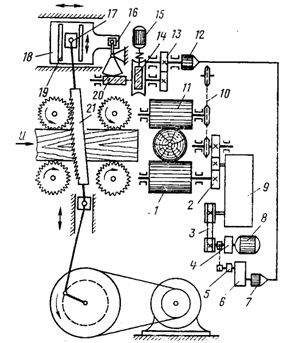
Rice. 1. Kinematic diagram of the sawmill frame
The frame of the sawmill is mounted on a base plate. A crankshaft with two flywheels and a drive pulley rotates in two main bearings mounted on a plate.The connecting rod of the I-beam is connected with the lower head to the crankshaft pin through a roller bearing, and the upper head is connected to the pin through the lower cross member of the saw frame through the needle bearing.
The lower and upper cross members of the saw frame are connected by round tubular supports. The textolite sliders with pins on the cross members of the saw frame are connected by tapered roller bearings.
The design of the saw frame allows the use of a hydraulic tensioner. Of its eight guides, four are prismatic and four are flat, which are attached in pairs to cast-iron plates mounted on the bed. The upper guide plates are mounted on a slide and are moved by the tilting mechanism of the saw frame, depending on the size of the plot Δ.
The individual drive of the four-roller feed mechanism, consisting of a thyristor drive, ensures a smooth adjustment of the log feed speed. The torque is transmitted to the lower rollers 1 from the engine 8 through an electromagnet, an electromagnetic clutch 4, a belt transmission 3, a gearbox 9 and gears 2. The upper rollers 11 rotate through a roller chain 10.
The size of the parcels is adjusted by changing the slide of the electromagnetic clutch 4, carried out by turning the dial of the centrifugal regulator 5. For this purpose, the operator turns on the servo motor 15, turning the dial to the appropriate angle, the rotation is carried out by the worm gear 14, gears 13, the selsyn sensor 12, the selsyn receiver 7 and the reducer 6.By changing the room Δ simultaneously through the worm gear 20 and the lever 16, the plate 18 moves in the horizontal plane with the guides 19 of the upper slide 17 of the saw frame and the inclination of the saw 21 changes.
A schematic circuit diagram of a sawmill frame 2P80 is shown in fig. 2. Its electrical equipment consists of 125 kW main shaft drive asynchronous motor M1, saw frame tilting mechanism drive M2 motor, hydraulic station motor MZ, lubrication pump motor M4 and automatic control system , based on a thyristor drive with a DC motor M5.
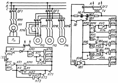
Rice. 2. Electrical schematic diagram of the sawmill frame 2P80
The maximum current protection of motors is provided by automatic switches: QF1 — motor M1, QF2 — motors M2, MZ, M4 and QF3 — control circuits. When QF3 is turned on, warning lamps HL1 and HL2 light up. The main shaft motor M1 is started using the linear contactor KM1, and the drive motor of the feed motor M5 is started using the contactor KM2.
The electrical control circuit includes: power circuits (driving motors); relay-contactor control circuits and circuits of automatic control system based on thyristor DC drive. To turn on the start of the saw frame drive when the upper gate is open, the main shaft and V-belt safety strips are removed, and when the saw frame is stopped, limit switches are used (whose block is indicated in Fig. 2 with the letters SQ).
The starting of the motor M1 with a wound rotor is carried out as a function of time by sequentially closing the acceleration relays KT1, KT2 and KT3, which with a given time delay gradually output three stages of the starting rheostat Rp using contactors K1, K2 and K3.
Pressing the start button SB1 (see Fig. 2) turns on the coil of the contactor KM3, which closes the power contacts KM3 of the motor M4 of the oil pump, the closing contact KM3 bypasses the button SB1.
The main motion motor M1 is started when the contact KV1 of the intermediate relay KV1 is closed. The coil of this relay receives power through the KT4 contact of the KT4 time relay, which when closed will close with a delay. Therefore, the relay KT4 provides a delay between the start of the motor M4 and M1.
When relay KV1 is turned on, relay KV2 turns on simultaneously, the closing contact of which KV2 energizes the coil of contactor KM1. The coil KM1, after receiving power, turns on the main contacts KM1 of the power circuit of the motor M1, and the rotor of the motor will start to rotate when the starting rheostat is fully set. After the acceleration contactors K1, K2 and K3 operate with deceleration, the motor rotor will rotate at maximum speed.
When the start of the motor M1 is complete, the opening contact K3 will simultaneously break the supply circuit of the contactors K1 and K2, and the contact K3 in the motor starter circuit of the feeder M5 will close and prepare it for starting. The motor is stopped by pressing the SB2 button.
The hydraulic system provides raising and lowering of the front and rear doors, on the welded casings of which the upper feed rollers are mounted.The gates are lifted into the upper position by hydraulic cylinders driven by a hydraulic station. The drive of the hydraulic station is provided by the motor M3, which is started at the push of a button, while the coil KM6 of the starter is energized, which closes the main contacts of KM6.
The tilt of the saw frame can be controlled manually (by pressing buttons SB3 and SB4) or automatically. With automatic control of the winding KM4 of the starter KM4 ("more") and KM5 of the starter KM5 ("less"), they receive power through the relay KV3, which turns on when the mode switch is in the "Automatic" position, that is when contact SQ1 is closed.
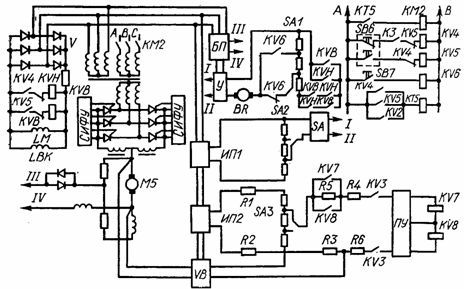
The thyristor power supply consists of an M5 DC motor and a thyristor converter. The thyristor converter (Fig. 9.2, c) is turned on by the starter KM2, through the contact KV3, the coil of which receives power when the contact of the time relay KT5, which is in its circuit, is closed. Timing relay KT5 will be energized when coils KV4 (forward motion) or KV5 (reverse motion) are energized.
If the log gets stuck while cutting, it is retracted by reversing the engine. Starting the feeder motor is not possible without the M1 motor running. This is ensured by the inclusion of contact K3 in the supply circuit KV4, which closes after the end of starting the motor M1. When the starter KM2 is turned on, the converter and the field windings LM of the motor are energized.
If the register is stuck, pressing the SB6 button turns off relays KV4 and KVB and relays KV5 and KVH turn on.In this case, the KVH relay closes its contacts in the supply circuit of the amplifier U, which is included in the thyristor converter, as a result, the polarity of the voltage at the output of the converter changes and the motor changes the direction of rotation.
The stability of the rotational speed when the load changes is ensured by a negative feedback, which is implemented by a BR tachogenerator with an LBL excitation coil. The armature BR is connected to the input of the amplifier V. The transient is forced by the use of regenerative braking in the thyristor converter circuit.
The feed rate is adjusted manually and automatically. For this, the SA switch is set. In manual feed rate regulation, the rate regulator is connected to amplifier U through circuits I and II. Speed controllers SA1 — SA3 are switches to panels to which MLT resistors are connected.
Moving the movable contact SA1 changes the control signal that enters the pulse-phase control system (SPPC) through the PU amplifier, which changes the firing angle of thyristors connected by a bridge rectifier circuit, due to which the speed of the motor M5 changes.
To automatically adjust the speed of the M5 engine through the SA switch, SA1 is disconnected from the amplifier block Y and connected to the amplifier Y SA2 — the journal diameter sensor. In this case, SA1 begins to receive power from SA2, which is a potentiometer connected to the stabilizing power supply IP1 and rotated by the power switching mechanism.
When the diameter of the journal changes, the slider of the potentiometer SA2 moves and the value of the control voltage applied to SA1 changes, therefore the feed rate changes with the change in the diameter of the journal. The speed value should match the saw frame slope, the speed is controlled by switching SA3.
The saw frame tilt sensor SA3 is connected to a stabilized power supply IP2 through resistors R1 and R2. The result is a stress proportional to the angle of inclination of the saw frame. This voltage is compared with the motor voltage M5, proportional to the speed, taken from the motor armature and fed to the resistor R3 through the rectifier block VB, it is subtracted from the output voltage of the tilt sensor of the saw frame.
With the motor in reverse, the VB block maintains a constant reference polarity. The mismatch signal is fed to the input of the intermediate amplifier PU through the resistors R4 — R6 and the closing contacts KV3 (closed during automatic adjustment). The signal is amplified and fed to the PU output, to which relays KV7 and KV8 are connected. They are triggered depending on the polarity of the error input signal.
So, as the feed rate increases, the voltage removed from the motor increases and the mismatch value is negative. In this case, the relationship between the feed rate and the inclination of the saw frame is broken. The amplified output signal from the PU amplifier includes the relay KV7, the closing contacts of which include the coil KM4.
KM4 closing contacts turn the M2 motor "forward" — increasing the tilt of the saw frame.At the same time, the output voltage at SA3 is increased by moving the potentiometer slider. The deviation signal begins to decrease to zero, after which the increase in the inclination of the saw frame stops. This maintains a match between the feed rate and the angle of the saw frame.
The control process proceeds in a similar way with a decrease in feed rate, but the error signal in this case has a positive sign. This causes relay KV8 to turn on, as well as KM5 and motor M2 to reverse. As the feed rate decreases, the slope of the saw frame also decreases. During regulation, the drive contacts KV7 and KV8 bypass the resistance R5, which makes it possible to force the process.
At the beginning of cutting, it is necessary to have a cutting speed equal to no more than 30% of the working feed speed. This is done in the following way. By pressing the button SB7, the relay KV6 is energized, the contacts of which are switched to the output SA1, so that a small control voltage is supplied through the closing contact KV6 to the input of the thyristor converter, which creates a low cutting speed.
After the end of the feed, the SB7 button is turned off and the device goes into working mode. The interruption of the automatic control system for the tilt of the saw frame during the feed is provided by connecting the closing contact KV6 to the supply circuit of the starter coils KM4 and KM5.