Electrical equipment for CNC lathes
 CNC lathes are used to machine workpieces such as turning bodies. We will consider the electrical equipment of CNC lathes using the example of a machine model 16K20F3. The lathe model 16K20F3 is widely used for processing external cylindrical surfaces (with stepped and curved profiles of varying complexity) and threading.
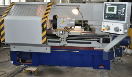
The general view of the machine is shown in fig
With regard to metal cutting machines, the following designation system is adopted (in addition to the group of letters and numbers that characterize the machine itself): F1 — machines with a digital display and preset coordinates, F2 — with CNC positioning systems, F3 — with contour CNC systems, F4 — multifunctional machines with automatic tool change.

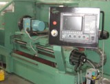
Rice. 1. General view of the machine model 16K20F3: 1 — bed, 2 — automatic gearbox, 3,5 — program control panels, 4 — electrical cabinet, 6 — spindle head, 7 — protective screen, 8 — back belt, 9 — hydraulic amplifier, 10 — hydroelectric station. A CNC system is understood as a set of specialized devices, methods and tools necessary to control the equipment. In fact, a CNC device is part of this system and is structurally implemented as a separate cabinet. Recently, in connection with the improvement of microprocessor technology, CNC devices based on it are sometimes built directly into the machine.
The model 16K20F3 lathe has a CNC contouring system. Contour systems ensure the movement of working bodies from one point to another along a given trajectory (straight line, circle, curve of a higher order, etc.). As a special case, the contour system provides machining along one of the coordinate axes.
The basis of the machine is a monolithic casting, on which the bed is located. The main drive motor is located inside the base. The support carriage and rear fluid run on bed guides. There is an automatic gearbox (AKS) on the dashboard. Six tools — milling cutters — can be mounted simultaneously on the rotating tool holder in the tool head.
chuck — a part of a metal cutting or woodworking machine that serves as a support for the spindle (front head) lathe or tool (grinder bed), or for a device supporting the workpiece (lathe tail).
CNC lathe model 16K20F3 provides:
-
movement of the caliper in two coordinates Z and X, automatic switching
-
spindle revolutions by switching AKS gears, changing tools by rotating the tool holder around the Z axis.
Machine control objects are: 1 — main drive, 2 — feed drives, 3 — tool holder drive, 4 — cooling system drive, 5 — hydraulic unit drive, 6 — lubrication system drive, 7 — drive of the feed pump.
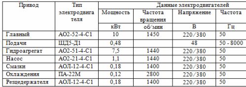
The technical characteristics of the drive motors are shown in Table 1.
The main motion drive contains an unregulated asynchronous electric motor and an automatic gearbox that provides nine spindle speeds. The power drives are controlled by a separate unit that provides the operation of the stepper motors of the caliper and the screw mechanism. The remaining drives are auxiliary and non-adjustable.
Table 1. Technical characteristics of electric motors of CNC lathe drives models 16K20F3
The machine control system includes (Fig. 2): CNC device model N22-1M — 1, relay device — 2, actuators — 3.
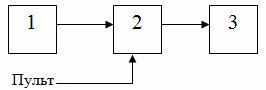
Rice. 2. Block diagram
The inclusion of any object in the machine can be done from the control panel of the machine or from the CNC device.
Control commands are decoded by code relays in the relay box. The included relays generate signals that are fed to the electromagnetic clutches of an automatic transmission or magnetic starters that control the operation of electric drives.
Spindle speed selection
Switching on the electric motor of the main movement is done by sending a command to the intermediate relays with switching on the corresponding contactor.
To activate the required rotational speed, signals are sent to the speed encoder relays.The connection of the contacts of these relays is a relay decoder that controls the activation of the electromagnetic clutch AKS.
Tool selection
The machine is equipped with a tool holder that allows the installation of six tools. Tool change is performed by rotating the tool holder to the designated position.
Control signals are sent to the tool change relays and tool position encoder relays with the motor on. The electric motor rotates the tool holder. When the specified position matches the tool position, the match relay is activated, giving a command to reverse the tool holder. The feedback relay then turns on, signaling the CNC to continue program execution.
Activation of the cooling and operation of the lubrication system
In automatic mode, the cooling motor turns on when a signal is applied to the intermediate relay, which energizes the corresponding contactor. During the cutting process, it is possible to start cooling with a switch from the control panel while the main drive is running.
The lubricator motor turns on each time the machine is first started and remains on for the time required for lubrication. During continuous operation of the machine, the lubrication cycle is set using a time relay with the required lubrication delay and pause. It is possible to manually turn on the lubrication during a pause using a button. This does not interrupt the lubrication cycle.
See also: Electric drive of lathes