Electrical equipment of CNC drilling machines
 The electrical equipment of CNC drilling machines will be considered on the example of a machine model 2R135F2.
CNC drilling machines model 2R135F2 are designed for processing body parts, as well as parts such as «flange», «cover», «plate», «bracket» and others. The machines allow drilling, drilling, countersinking, threading and other operations.
The general view of the machine is shown in fig.
The workpiece to be processed is fixed on the table. The tower can hold six instruments. When specifying machining, the table moves along the X, Y axes to the position specified by the program. After the table is installed, the support is activated.
Slider movement during machining is down the Z axis in accordance with the program. The slider returns to its original up position until the limit switch is actuated. Tool change is done by rotating the turret to the upper slide position.
Spatial movements along the axes of the table and sliding axes are controlled by position sensors, continuous information from which is transmitted to the CNC block. The turret contains six end switches that determine the working position of one of the tools.
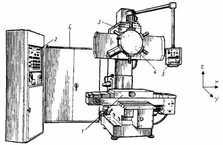
Fig. 1. General view of the machine: 1 — table, 2 — CNC device, 3 — support, 4 — tower, 5 — control panel, 6 — cabinet for relay automation.
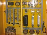
The electrical equipment of the machine consists of a relay automation cabinet, a numerical control device (CNC), and machines and devices installed directly on the machine structure.
The electrical cabinet contains:
1 — relay panel on which intermediate relays and relays for communication with the CPU unit are mounted,
2 — power panel, on which a controlled thyristor converter, transformers, magnetic starters, protective devices, rectifiers of power supplies are installed,
3 — input switch for connecting the machine to the electrical network.
The machine is equipped with:
1 — electric motors,
2 — electromagnetic clutches of the ETM type for regulating the speeds of movement of the working bodies of the machine,
3 — feedback sensors for monitoring the position of the working organs of the machine,
4 — limit switches, limiting the range of movement of the working bodies of the machine,
5 — control panel with buttons and indicators,
6 — a lamp for lighting the working area of processing.
The carriage drive is controlled by a thyristor converter, which provides regulated operation of the DC motor in a programmed feed mode. Electromagnetic clutches provide fast and slow movement of the caliper during positioning and stopping.
The drive of the main movement (spindle) contains an unregulated asynchronous electric motor and an automatic gearbox with electromagnetic clutches, which provides 19 revolutions of the spindle.
The movement of the table is carried out along two coordinate axes with the help of asynchronous electric motors. The speed of the table movement is regulated by the clutches on the X and Y axes. The clutches provide fast, slow motion and stop of the table drives.
The tower is driven by an electric motor. Tightening and squeezing the head is done using a clutch.
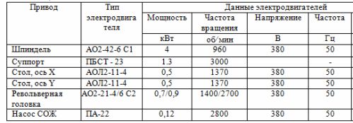
The technical characteristics of the electric motors of the drives of the CNC drilling machine are shown in Table 1.
The general block diagram of the programmed control of the working organs of the machine is shown in fig. 2.
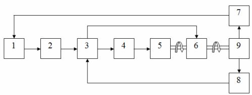
Rice. 2. Block diagram for controlling the working organs of the machine: 1 — CNC, 2 — block of code relays, 3 — block of intermediate relays, 4 — block of magnetic starters, 5 — electric motors, 6 — block of electromagnetic clutches, 7 — sensors for the position of working bodies of the machine, 8 — road switches, 9 — working bodies of the machine.
In the carriage control circuit there is an additional controlled converter, which provides the ability to smoothly adjust the speed of rotation of the motor.
The inclusion of any object in the machine can be done from the control panel of the machine or from the CNC device.
CNC control commands are decoded by code relays in the relay unit. The switched relays generate signals that are fed to the intermediate relays.These relays include electromagnetic clutches or magnetic starters that control the operation of electric motors.
Positioning of the table and slide is performed at fixed values of the movement speeds. The TNC compares the distance from the actual position of the workpiece to the one programmed with the settings. If this distance is equal to the set value, the movement speed is changed. The drive is stopped at the program point.
The part is machined with programmable slide feed rates.
Switch on the electrical equipment of the machine
The electrical equipment of the machine is connected to the mains via an input circuit breaker. The voltage supply to all drive circuits of the machine is carried out by a contactor when the «Start» button is pressed. Switching off is done using the «Stop» button. The spindle, table and turret motors are powered by circuit breakers. To start, you must turn on the circuit breakers and press the «Start» button.
Caliper management
The electric drive provides movement of the slider along the Z axis in the machine coordinate system. The electric caliper drive operates in positioning and machining modes. Down positioning mode involves rapid travel to the distance specified by the set point, followed by slow travel to the surface of the workpiece, provided that the speed is reduced in two stages.
Programmable rate feed is performed in the downward direction during machining (eg drilling). A slow motion occurs when the tool is pulled from the workpiece to the surface in an upward direction.Retraction of the tool "up" from the workpiece to the starting position is carried out in rapid traverse mode.
The regulation of the speed of movement is carried out by means of two electromagnetic couplings (fast and slow movements, respectively) and by changing the speed of rotation of the motor by changing the resistance of the set value at the input of the controlled converter. The regulator is a potentiometer consisting of a set of resistors connected in series.
In positioning mode, fast and slow movement speeds are fixed. In feed mode, the speed is adjusted according to the programmed value of the code coming from the CNC. Control signals from the CNC unit are fed to receiving relays, which with their contacts switch various circuits in the control circuit of the drive.
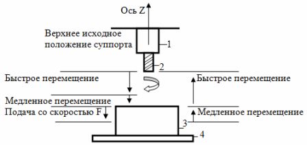
Rice. 3. Diagram of the movement of the support when processing a part: 1 — support, 2 — tool, 3 — part, 4 — table.
Basic motion control
The spindle drive contains an asynchronous reversible electric motor, an automatic gearbox (AKS) with electromagnetic clutches. The main motion motor in all machining operations, except threading, runs continuously, with the correct direction of rotation (clockwise).
When the motor is reversed in threading mode, the timing is provided by a timing relay that allows the reverse direction of rotation. While the time relay is on, setting a new direction is not possible.
Rotation from the motor to the spindle is transmitted through AKC gears controlled by electromagnetic clutches. Clutches provide adjustment of a given rotational speed.Binary - The decimal speed code is fed to the relay. The contacts of these relays form a spindle speed code decoder and turn on the electromagnetic clutches.
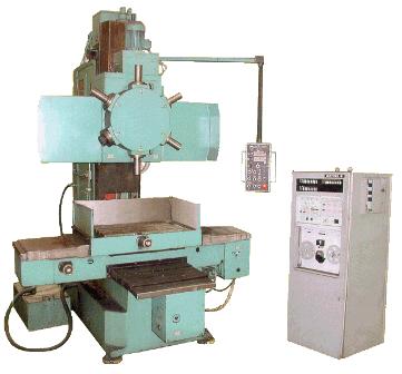
Table drive control
The table moves along the X, Y axes of the machine coordinate system. The movement is provided by two reversible asynchronous motors. The table speed control is two-stage. Fast and slow movement during table positioning is accomplished by means of electromagnetic clutches that include gears on the reducer.
Directional signals are received from the CNC module: "right" on the X axis, "forward" on the Y axis, and "fast" or "slow" speed signals. The receiving relays are turned on according to the signals of the CNC unit, which in turn turns on the corresponding motion couplers and contactors. The contactors ensure the connection of the motors to the power circuits. When the contactors are turned off, the brake clutches are activated, fixing the position of the table in the specified position. The movement of the table along the coordinates is limited by the limit switches.
Relay contacts are introduced into the circuit of the contactor coils, providing a time delay to set the reverse direction of rotation when the motor is reversed. While these relays are on, a new direction of rotation cannot be set.
Tower control
Turret drive provides tool change by rotating the turret. The drive contains an asynchronous two-speed electric motor and an electromagnetic clutch. The disengaged clutch engages the turret in the operating position. The change in the position of the head takes place after its release.
The process of tightening and loosening the head is carried out by a low-speed electric motor when the stator windings are connected according to the «delta» scheme. In this case, the clutch must be engaged. The rotation of the head is carried out by the motor at high speed (double star scheme), also with the clutch engaged.
The contactors and clutch turn on when the tool code is received. If the code does not match the head position, the tool change process begins.