Logic modules LOGO! for industrial automation
 Microprocessor devices are widely used in the automation of general industrial, transport and household devices. Due to the flexibility and low cost of microprocessor devices, their share in automation devices is constantly increasing. In the initial stage of using microprocessor devices, the main limiting factor was, with the low cost of the microcontrollers themselves, the significant cost of creating their software, which was developed in low-level programming languages and required highly skilled programmers.
This problem was solved by creating functionally complete microprocessor modules with built-in basic software and additional expansion modules. The connection of the base modules to the expansion modules is carried out through special connectors, which exclude the connection of modules that, according to some criteria (for example, supply voltage), cannot be connected to the base module.
The modules are programmed in specialized high-level languages, such as Step 5 or Step 7, which allow you to compile a program in the form of a block diagram or contact diagram, or in the form of a system of logic equations. The compilation of such programs into machine codes is carried out taking into account the specific nomenclature of the installed modules. The programmer does not need special knowledge of the structure and commands of the microprocessors included in the modules, but only needs knowledge of the functioning of the developed technical system.
The company, the developer of the modules, creates specialized software for a personal computer with a convenient interface that provides all stages of system development and programming of microprocessor modules directly through the ports of a personal computer or an additional device connected to the computer. This concept was implemented by SIEMENS in the creation of the LOGO! microprocessor module set.
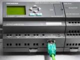
LOGO! is a universal logic microprocessor module from Siemens… LOGO! includes microprocessor control unit, control panel and backlit display, power supply, expansion module interface, programming module interface (card) and PC cable.
THE LOGO! includes standard out-of-the-box functions that are often used in practice, for example: on and off delay functions, pulse relay, programmable keys, clock switch, digital and analog flags, inputs and outputs depending on the device type.
Types of LOGO!
Basic is available in two voltage classes:
-
Class 1 <24 V, i.e. 12 V DC current, 24 V DC current, 24 V AC current;
-
Class 2> 24 V, i.e.115 … 240 VDC and alternating current;
in options:
-
with LCD display (LCD): 8 inputs and 4 outputs;
-
without display («LOGO! Pure»): 8 inputs and 4 outputs.
Each class consists of 4 subunits (SU), is equipped with an expansion interface and provides 33 ready-to-use basic and special functions for developing a switching program.
Expansion modules
-
LOGO! Digital modules are available for all voltages and have 4 inputs and 4 outputs.
-
Analog modules LOGO! Available for 12 and 24 VDC with two analog inputs or two PT100 inputs.
-
The digital and analog modules consist of two subunits. Each of them has two expansion interfaces for connecting additional modules.
Any device LOGO! Basic Basic can only be expanded with expansion modules of the same voltage class. Mechanical coding (pins in the case) prevents the connection of devices of different voltage classes. Exception: The left interface of the analog or communication module is electrically isolated. Therefore, these expansion modules can be connected to devices with different voltage classes.
Elements in the LOGO!
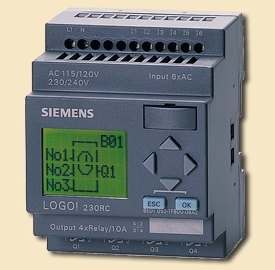
LOGO! They differ in the type (constant = or variable ~) and the value of the supply voltage, the type of outputs (relay or transistor), the presence or absence of a liquid crystal display. The diversity of LOGO! allows you to choose the most suitable set, with minimal excess of technical means, realizing a specific technical problem.
Designation of elements:
-
Option 12 — 12 V DC.
-
Option 24 — 24 VDC.
-
230 — 115/240 VAC optional.
-
R — relay outputs (without R — transistor outputs).
-
C — built-in 7-day clock.
-
o — no display option.
-
DM — digital module.
-
AM is an analog module.
-
CM — communication module (eg AS interface).
LOGO!

(1) — of which you can alternatively use 2 analog inputs with a signal range of 0 … 10 V and 2 fast inputs. (2) — 230 V AC options — inputs in two groups of 4. Within a group only the same phase is possible, different phases are possible between groups. (3) — digital inputs can work with direct and reverse polarity. (4) — with you can select the signal range 0 … 10 V or 0 … 20 mA.

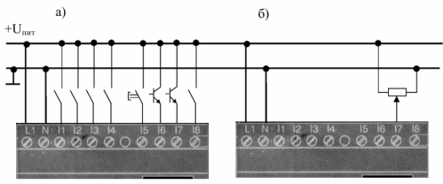
Contact LOGO! 12/24 RC sensors: a) discrete, with contact and non-contact outputs, b) analog (0 — 10 V)
LOGO! Functions
LOGO! in programming mode provides you with various items that are divided into lists:
-
CO — list of connectors (inputs / outputs)
-
GF — list of basic functions AND [AND], OR [OR],
-
SF — list of special functions
-
BN is a list of blocks ready for use in the circuit program.
All lists represent the items available in LOGO!. Typically, these are all connectors, all basic functions and all special functions known to LOGO!. This also includes any blocks you have created in LOGO! until the list is called. LOGO! does not display all items if there is no free space in memory or the maximum possible number of blocks is reached. In this case, the next block cannot be inserted.
Constants and connectors (Co) are inputs, outputs, bits of memory, and fixed voltage levels (constants).
Inputs:
1) Digital inputs
Digital inputs are marked with the letter I.The digital input numbers (I1, I2, …) correspond to the input pin numbers of the LOGO! The numbering of the inputs of the base unit and the expansion units is directly in the order in which the units are installed.
2) Analog inputs
THE LOGO! 24, LOGO! 24o, LOGO! 12 / 24RC and LOGO! The 12 / 24RCo has inputs I7 and I8, which can also be programmed for use as analog inputs AI1 and AI2. If these inputs are used as I7 and I8, then the input signal is interpreted as a digital value. If used as AI1 and AI2, the signals are interpreted as analog values. When an analog module is connected, its inputs are numbered after the existing analog inputs.
In the case of special functions that on the input side make sense to connect only to analog inputs when the input signal is selected in programming mode, only analog inputs AI1 … AI8, analog flags AM1 … AM6, the analog outputs of the modules that offer are numbered as outputs AQ1 and AQ2.
Outputs:
1) Digital outputs
The digital outputs are marked with the letter Q. The output numbers (Q1, Q2, … Q16) correspond to the LOGO! output pin numbers. The output numbers are numbered consecutively, starting with the base module and continuing in the order in which the modules are installed. In addition, it is possible to use 16 outputs that are not connected to the blocks. They are marked with an X and cannot be reused in a chain program (unlike, for example, flags).
All programmed unconnected outputs appear in the list, as well as one unprogrammed unconnected output.The use of an unconnected output makes sense, for example, with the special function «Message texts», if only the message text is relevant for the circuit program.
2) Analog outputs
The analog outputs are marked with the letters AQ. Two analog outputs are available, namely AQ1 and AQ2. Only an analog value can be connected to the analog output, ie. function with analog output or AM analog flag.
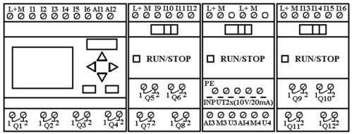
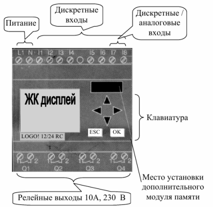
Rice. 1. Front panel view of LOGO!
Flags
Flags are marked with the letters M or AM. These are virtual outputs that have the same value at their output as at their input. IN THE LOGO! there are 24 digital flags M1 … M24 and 6 analog flags AM1 … AM6.
The start flag M8 is set in the first cycle of the user program and therefore can be used as the start flag in your chain program. It is reset automatically after the first cycle of the program. In all subsequent cycles, the M8 flag can be used in the same way as the other flags.
Logic signal levels
Signal levels are indicated by hi and lo. If the state «1» = hi or «0» = lo must be constantly present on the block, then a fixed level or constant value hi or lo is applied to the input. Open Connectors If a block connector is not used, it may be marked with an x.
List of main features — GF
The main functions are simple logical elements of Boolean algebra.
The GF list contains blocks of basic functions that you can use in your schema. The following basic functions are available:
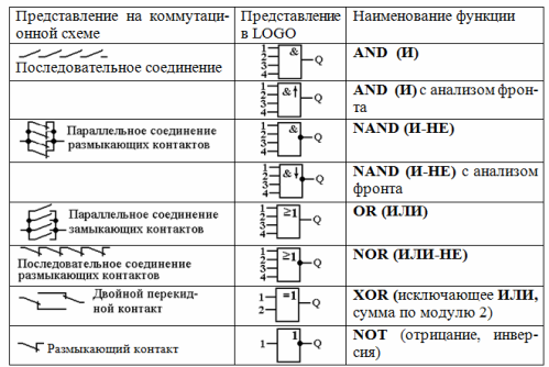
List of special functions — SF
When you enter a circuit program in LOGO! you will find special function blocks in the SF list.The inputs of the special functions can be individually inverted, i.e. the switching program converts the logic «1» of the input to the logic «0»; and converts logical «0» to logical «1». The table shows whether the corresponding function is parameterizable (REM).
The following special features are available:
-
Delay on power-up
-
Slow down
-
On/off delay
-
Delay when powering on with memory
-
Interval time relay (short pulse generation)
-
Edge-triggered time relay
-
Asynchronous pulse generator
-
Random pulse generator
-
Stair light switch
-
Dual function switch
-
Switch for seven days
-
Switch twelve months
-
Countdown timer
-
Working time counter
-
Threshold switch
-
Analog threshold switch
-
Analog differential threshold switch
-
Analog comparator
-
Monitoring of analog values
-
Analog amplifier
-
Self-locking relay (RS flip-flop)
-
Impulse relay
-
Program switch
-
Shift register
An example of using the logic module LOGO!
The use of microprocessor systems in electrical engineering on the example of the use of PLC
LOGO!
LOGO! Soft Comfort is available as a software package for PC. This software includes the following features:
- a graphical interface for creating a circuit program in offline mode in the form of a circuit logic diagram (contact diagram / circuit diagram) or a functional block diagram (functional plan);
- simulation of your circuit program on a computer;
- generate and print a program schematic block diagram;
- storing the program on a hard disk or other storage medium;
- comparison of switching programs;
- convenient parameterization of blocks;
- transferring the circuit program from LOGO! to the computer and from the computer to LOGO!;
- reading the working time counter;
- set a time;
- transition from summer to winter time and vice versa;
- online testing, display of states and current values of LOGO! In RUN mode;
- stopping the execution of the circuit program by the computer (STOP).
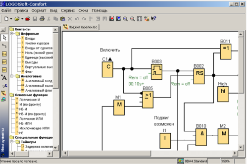
LOGO! Soft Comfort main window in FBD mode (FBD editor)
An example. An electrical network model in LOGO! Soft Comfort

Rice. 2. Configuration of the protected network RU1, RU2 — switchgear; P1, P2 — the first and second groups of users; SF1, SF2 — first and second breakers; K1, K2 the first and second short-circuit points; I1, I2 — currents in network sections
From the switchgear RU1, several electrical lines depart, one of which is protected by a circuit breaker SF1. Switchgear RU2 is fed from this line, one of the output lines of which is protected by circuit breaker SF2.
A short circuit can occur in section 1 (point K1) or in section 2 (point K2), while the short circuit (short circuit) must be disconnected closest to the short circuit point. switch. However, if the nearest switch is faulty, then there is a short circuit. must be turned off by a switch closest to the power source.
The electrical network model in LOGO! Soft Comfort is shown in Figure 3.
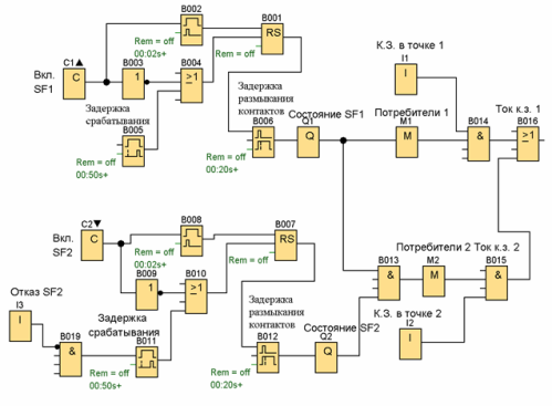
Rice. 3. Model of the electrical network in LOGO! Soft Comfort
Breaker SF1 is simulated with button C1 and blocks B001,… B006 and Q1.
The C1 button corresponds to the machine's on/off handle.Trigger B001 simulates the machine's mechanical latch that holds the contacts in a closed or open state.
Block B002 simulates a "break lever" that allows you to turn off the machine when the on / off handle is engaged.
The B003 inverter ensures that the machine is turned off when the handle is turned off.
Block B005 corresponds to a release which, through block B004, turns off the circuit breaker when a «1» is applied to its input Trg. The release works with a time delay, which consists of a fixed and an adjustable part.
The state of the SF1 machine contacts is determined by the Q1 output. Block B006 simulates the contact travel time while the circuit is fully open.
Block I1 simulates a short circuit. at point K1, block M1 shows the presence of voltage to consumers of the first group, block B016 simulates the emergency current in the first section.
The second section of the network is simulated in a similar way, but with the help of input I3, the fault of the breaker SF2 is simulated.