Coordination of structural logic circuits with power circuits
The development of structural logic circuits on non-contact logic elements almost always implies that the switching of the power circuits that will be controlled by the logic circuit must also be carried out on non-contact elements, which can be thyristors, triacs, optoelectronic devices.
An exception to this rule can only be relays for monitoring voltage, current, power and other parameters that have not yet been transferred to non-contact elements. The difference in the parameters of the output signals of the structural logic circuits and the parameters of the switching equipment necessitates solving the problem of matching these parameters.
The matching task is to convert the output signal of the logic circuit into a signal with such parameters that would exceed the analogous parameters of the input circuits of contactless switching equipment.

The solution to this problem depends on the load parameters of the power circuit.For low-power loads or switching signal circuits, no special coordination may be required at all. In this case, the load current of the output logic element must be greater or, in the extreme case, equal to the input current of the optocoupler, i.e. LED current or the sum of LED currents if the output function controls multiple power circuits.
When this condition is met, no agreement is required. It is enough just to choose an optothyristor with an LED current less than the load current of the output logic element, and the photothyristor current is greater than the rated current of the included electrical circuit.
In such circuits, the output signal from the logic element is fed to the LED of an optocoupler, which in turn controls the switching of the low-current power circuit of the load or signal element.
If such an optocoupler cannot be selected, in such cases it is sufficient to select the last element of the logic circuit, which implements the logic function with an increased branching ratio or with an open collector, with which you can obtain the necessary parameters of the output logic signal and directly apply it to the LED of the optocoupler. In this case, it is necessary to select an additional source and calculate the limiting resistor of the open collector (see Fig. 1).
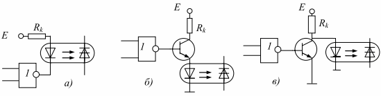
Rice. 1. Schemes for connecting optocouplers to the output of logic elements: a — on a logic element with an open collector; b — inclusion of an optocoupler in the emitter of the transistor; c — common emitter circuit
So, for example, the resistor Rk (Fig. 1 a) can be calculated from the following conditions:
Rk = (E-2.5K) / Iin,
where E is a source voltage, which can be equal to the source voltage for logic chips, but must be greater than 2.5K; K is the number of LEDs connected in series to the output of the microcircuit, while it is considered that approximately 2.5 V falls on each LED; Iin is the input current of the optocoupler, that is, the current of the LED.
For this switching circuit, the current through the resistor and the LED should not exceed the current of the chip. If you plan to connect a large number of LEDs to the output of the microcircuit, then it is recommended to choose logic with a high threshold as logic elements.
The single signal level for this logic reaches 13.5 V. Thus, the output of such logic can be applied to the input of a transistor switch and up to six LEDs can be connected in series to an emitter (Fig.1 b) (the diagram shows one optocoupler). In this case, the value of the current-limiting resistor Rk is determined in the same way as for the circuit in fig. 1 a. With low-threshold logic, LEDs can be switched in parallel. In this case, the resistance value of the resistor Rk can be calculated by the formula:
Rk = (E — 2.5) / (K * Iin).
The transistor must be selected with an allowable collector current exceeding the total current of all LEDs connected in parallel, while the output current of the logic element must reliably open the transistor.
In fig. 1 c shows a circuit with the inclusion of LEDs to the collector of the transistor. The LEDs in this circuit can be connected in series and in parallel (not shown in the diagram). The resistance Rk in this case will be equal to:
Rk = (E — K2.5) / (N * Iin),
where — N is the number of parallel LED branches.
For all calculated resistors, it is necessary to calculate their power according to the well-known formula P = I2 R. For more powerful users, it is necessary to use thyristor or triac switching. In this case, the optocoupler can also be used for galvanic isolation of the structural logic circuit and the power circuit of the executive load.
In switching circuits of asynchronous motors or three-phase sinusoidal current loads, it is recommended to use triacs that are triggered by optical thyristors, and in switching circuits with DC motors or other DC loads, it is recommended to use thyristors... Examples of switching circuits for AC and DC circuits are shown in Fig. 2 and fig. 3.

Rice. 2. Communication schemes of a three-phase asynchronous motor
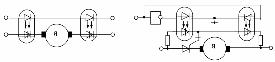
Rice. 3. Commutation circuit of a DC motor
Figure 2a shows the switching diagram of a three-phase asynchronous motor whose rated current is less than or equal to the rated current of the optical thyristor.
Figure 2b shows the switching scheme of an induction motor, the rated current of which cannot be switched by optical thyristors, but is less than or equal to the rated current of the controlled triac. The nominal current of the optical thyristor is selected according to the control current of the controlled triac.
Figure 3a shows the switching circuit of a DC motor whose rated current does not exceed the maximum allowable current of the optothyristor.
Figure 3b shows a similar switching scheme of a DC motor whose rated current cannot be switched by optical thyristors.