Thyristors: principle of operation, design, types and methods of inclusion
The principle of operation of the thyristor
A thyristor is a power electronic, not fully controllable switch. Therefore, sometimes in the technical literature it is called a single-operation thyristor, which can be switched to a conducting state only by a control signal, i.e. it can be turned on. To turn it off (in direct current operation), special measures must be taken to ensure that the direct current drops to zero.
A thyristor switch can only conduct current in one direction, and in the closed state it is able to withstand both forward and reverse voltage.
The thyristor has a four-layer p-n-p-n structure with three leads: Anode (A), Cathode (C) and Gate (G), which is shown in Fig. 1
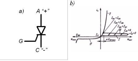
Rice. 1. Conventional thyristor: a) — conventional graphic designation; b) — volt-ampere characteristic.
In fig. 1b shows a family of output static I — V characteristics at different values of the control current iG. The limiting forward voltage that the thyristor can withstand without turning it on has maximum values at iG = 0.As the current increases, iG decreases the voltage that the thyristor can withstand. The on state of the thyristor corresponds to branch II, the off state corresponds to branch I, and the switching process corresponds to branch III. The holding current or holding current is equal to the minimum allowable forward current iA at which the thyristor remains conducting. This value also corresponds to the minimum possible value of the forward voltage drop across the on thyristor.
Branch IV represents the dependence of the leakage current on the reverse voltage. When the reverse voltage exceeds the value of UBO, a sharp increase in the reverse current begins, associated with the failure of the thyristor. The nature of the breakdown may correspond to an irreversible process or an avalanche breakdown process inherent in the operation of a semiconductor zener diode.
Thyristors are the most powerful electronic switches, capable of switching circuits with voltages up to 5 kV and currents up to 5 kA at a frequency of no more than 1 kHz.
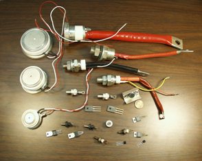
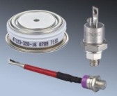
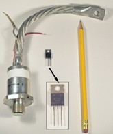
The design of thyristors is shown in fig. 2.
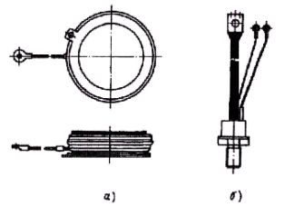
Rice. 2. The design of thyristor boxes: a) — tablet; b) — a pin
DC thyristor
A conventional thyristor is turned on by applying a current pulse to the control circuit with positive polarity relative to the cathode. The duration of the transient during turn-on is significantly affected by the nature of the load (active, inductive, etc.), the amplitude and rate of rise of the control current pulse iG, the temperature of the semiconductor structure of the thyristor, the applied voltage and load current .In a circuit containing a thyristor, there should be no unacceptable values of the rate of rise of the forward voltage duAC / dt, where spontaneous activation of the thyristor can occur in the absence of the control signal iG and the rate of rise from the current diA / dt. At the same time, the slope of the control signal must be high.
Among the ways to turn off thyristors, it is customary to distinguish between natural turn-off (or natural switching) and forced (or artificial switching). Natural commutation occurs when thyristors operate in alternating circuits at the moment the current drops to zero.
The methods of forced switching are very diverse. The most typical of them are the following: connecting a pre-charged capacitor C with a switch S (Figure 3, a); connecting an LC circuit with a pre-charged capacitor CK (Figure 3 b); the use of the oscillatory nature of the transient process in the load circuit (Figure 3, c).
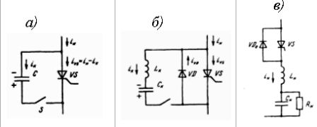
Rice. 3. Methods for artificial switching of thyristors: a) — by means of charged capacitor C; b) — by means of oscillatory discharge of the LC circuit; c) — due to the fluctuating nature of the load
When switching according to the diagram in fig. 3 and connecting a switching capacitor of reverse polarity, for example to another auxiliary thyristor, will cause it to discharge to the conducting main thyristor. Since the discharge current of the capacitor is directed against the forward current of the thyristor, the latter decreases to zero and the thyristor turns off.
In the diagram of fig. 3, b, the connection of the LC circuit causes an oscillating discharge of the switching capacitor CK.In this case, at the beginning, the discharge current flows through the thyristor opposite to its forward current, when they become equal, the thyristor turns off. In addition, the current of the LC-circuit passes from the thyristor VS to the diode VD. As the loop current flows through the diode VD, a reverse voltage equal to the voltage drop across the open diode will be applied to the thyristor VS.
In the diagram of fig. 3, connecting a thyristor VS to a complex RLC load will cause a transient. With certain parameters of the load, this process can have an oscillatory character with a change in the polarity of the load current in. In this case, after turning off the thyristor VS, the diode VD turns on, which begins to conduct a current of opposite polarity. Sometimes this method of switching is called quasi-natural because it involves a change in the polarity of the load current.
AC thyristor
When the thyristor is connected to the AC circuit, the following operations are possible:
-
switching on and off the electric circuit with active and active-reactive load;
-
change in average and effective current values through the load due to the fact that it is possible to adjust the timing of the control signal.
Since the thyristor switch is capable of conducting electric current in only one direction, then for the use of alternating current thyristors, their parallel connection is used (Fig. 4, a).
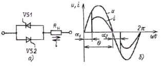
Rice. 4. Anti-parallel connection of thyristors (a) and the shape of the current with an active load (b)
Average and effective current vary due to a change in the time at which opening signals are applied to thyristors VS1 and VS2, i.e. by changing the angle and (Fig. 4, b).The values of this angle for thyristors VS1 and VS2 during regulation are simultaneously changed by the control system. The angle is called the control angle or firing angle of the thyristor.
The most widely used in power electronic devices are phase (Fig. 4, a, b) and thyristor control with pulse width (Fig. 4, c).
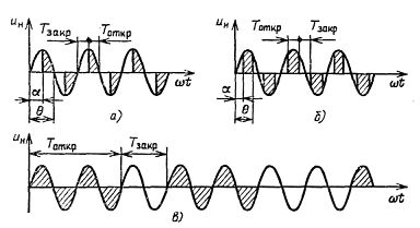
Rice. 5. Type of load voltage at: a) — phase control of the thyristor; b) — phase control of a thyristor with forced commutation; c) — pulse width thyristor control
With the phase method of thyristor control with forced commutation, regulation of the load current is possible both by changing the angle ? and angle ?... Artificial switching is carried out using special nodes or using fully controlled (locking) thyristors.
With pulse width control (pulse width modulation — PWM) during Totkr, a control signal is applied to the thyristors, they are open and the voltage Un is applied to the load. During the Tacr time, the control signal is absent and the thyristors are in a non-conducting state. RMS value of the current in the load

where In.m. — load current at Tcl = 0.
The current curve in the load with phase control of the thyristors is non-sinusoidal, which causes distortion of the shape of the voltage of the supply network and disturbances in the work of consumers sensitive to high-frequency disturbances - the so-called occurs. Electromagnetic incompatibility.
Locking thyristors
 Thyristors are the most powerful electronic switches used to switch high voltage, high current (high current) circuits.However, they have a significant drawback — incomplete controllability, which is manifested in the fact that in order to turn them off, it is necessary to create conditions for reducing the forward current to zero. This in many cases limits and complicates the use of thyristors.
To eliminate this drawback, thyristors have been developed that are locked by a signal from the control electrode G. Such thyristors are called gate-off thyristors (GTO) or dual-operation.
Locking thyristors (ZT) have a four-layer p-p-p-p structure, but at the same time have a number of significant design features that give them a completely different from traditional thyristors - the property of full controllability. The static I-V characteristic of turn-off thyristors in the forward direction is identical to the I-V characteristic of conventional thyristors. However, the lock-in thyristor is usually unable to block large reverse voltages and is often connected to an anti-parallel diode. In addition, lock-in thyristors are characterized by significant forward voltage drops. To turn off the locking thyristor, it is necessary to apply a powerful pulse of negative current (approximately 1: 5 in relation to the value of the constant off current) to the circuit of the closing electrode, but with a short duration (10-100 μs ).
Lock-in thyristors also have lower cutoff voltages and currents (by about 20-30%) than conventional thyristors.
The main types of thyristors
 With the exception of lock-in thyristors, a wide range of thyristors of various types has been developed, differing in speed, control processes, direction of currents in the conducting state, etc.Among them, the following types should be noted:
-
thyristor diode, which is equivalent to a thyristor with an antiparallel connected diode (Fig. 6.12, a);
-
diode thyristor (dynistor), switching to a conductive state when a certain voltage level is exceeded, applied between A and C (Fig. 6, b);
-
locking thyristor (Fig. 6.12, c);
-
symmetrical thyristor or triac, which is equivalent to two antiparallel connected thyristors (Fig. 6.12, d);
-
high-speed inverter thyristor (off time 5-50 μs);
-
field thyristor, for example, based on a combination of a MOS transistor with a thyristor;
-
optical thyristor controlled by light flux.
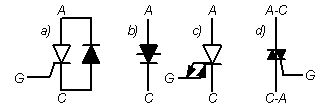
Rice. 6. Conventional graphic designation of thyristors: a) — thyristor diode; b) — diode thyristor (dynistor); c) — locking thyristor; d) — triac
Thyristor protection
Thyristors are critical devices for the rate of rise of the forward current diA / dt and the voltage drop duAC / dt. Thyristors, like diodes, are characterized by the phenomenon of reverse recovery current, whose sharp drop to zero aggravates the possibility of overvoltages with a high duAC / dt value. Such overvoltages are the result of a sudden interruption of the current in the inductive elements of the circuit, including small inductances installation. Therefore, various CFTCP schemes are usually used to protect thyristors, which in dynamic modes provide protection against unacceptable values of diA / dt and duAC / dt.
In most cases, the internal inductive resistance of the voltage sources included in the circuit of the included thyristor is sufficient so that no additional inductance LS is introduced.Therefore, in practice, there is often a need for CFTs that reduce the level and speed of tripping surges (Fig. 7).
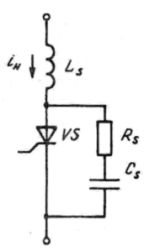 Rice. 7. Typical thyristor protection circuit
RC circuits connected in parallel with the thyristor are usually used for this purpose. There are various circuit modifications of RC circuits and methods of calculating their parameters for different conditions of use of thyristors.
For lock-in thyristors, circuits are used to form a switching path, similar in circuit to CFTT transistors.