Examples of electric drive schemes for mechanisms of centrifugal and reciprocating types
 In fig. 1 a shows a technological diagram of pumps of a mine drainage installation designed to pump groundwater from the heels of mine shafts and buried faces. The installation includes two pumps 1H and 2H with filling tanks 1B and 2B, which ensure constant charging of the pumps.
The pumps are driven in rotation by asynchronous motors with squirrels 1D and 2D, which for greater reliability are connected to different bus sections of the lowering substation (Fig. 1, b). If the water level in the pit is below the working level, then the pumps do not pump the water. When the water exceeds the working level, one of the pumps is put into operation. When the water level rises above the emergency level, a second backup pump is connected to work.
Scheme movement powered by electricity allows different control of the pump motors:
• automatically depending on the water level in the pit,
• remotely (from the control room),
• local village control buttonslocated directly at the pumps.
Auto AU and remote control selection is via 1UP and 2UP universal switches. Switches 1PP and 2PP allow you to select a control method for each motor: remote control and local using buttons 1KU and 2KU. The software switch allows for uniform wear of the equipment to alternately use 1D and 2D motors as the running motor.
Automatic engine start the working pump is implemented using a float switch 1PR, which controls the working water level. The backup pump motor is switched on by float relay 2PR, which controls the emergency level.
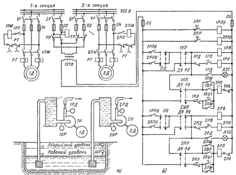
Rice. 1. Dewatering installation (a) and electrical circuit (b).
If after the delay time of the relay 1PB or 2PB the pump does not create the required pressure, the motor is disconnected from the network. The engine will not start even if the pump is not completely filled with water (insufficient water level in the filling tank and the contacts of the filling control relay 1BP or 2BP are open).
In fig. 2 shows a diagram of an automated electric drive of a reciprocating compressor. The asynchronous compressor motor can be started from the compressor installation site using the 2KP button, as well as from the control room using the 1KP button. Start permission is given through the 2RP relay if the pressure in the air receiver (receiver) is less than normal. In this case, the closing contact of the pressure switch 1RP in the circuit of the relay 2RP closes, the coil of the relay 2RP flows current, and the closing contact 2RP in the circuit of the contactor of the KL line closes.
After switching on the contactor KL, the coil of the electrohydraulic valve 1KEG is energized, which supplies cooling water to the compressor. After some time, the RV relay receives power to the 4RP relay, which turns on the 2KEG valve. This valve will shut off the outlet of air from the compressor to the atmosphere. The delay of the PB relay is slightly longer than the engine start time, so the 2KEG valve is open and the engine start is facilitated.
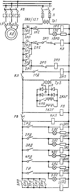
Rice. 2. Diagram of the electrical drive of a reciprocating compressor.
If the air flow is low and the pressure in the receiver exceeds the norm, then the 1RD contact in the 3RP relay circuit closes. The latter, with its opening contact, turns off the relay 2RP. The contact circuit KL loses power, and the engine is disconnected from the network. When the air flow increases and the pressure in the receiver decreases compared to the norm, the pressure switch will close its upper contact 1RD and will turn on relay 2RP. The KL contactor coil will again be energized and the compressor will start in the same manner as described above.
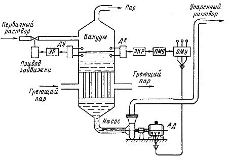
Rice. 3. Scheme of the liquid evaporation plant
The circuit provides automatic shutdown of the engine if the refrigerator air pressure, the pressure of the cooling water and oil supplied to the main bearings, and the oil temperature are out of range. The specified parameters are controlled using a pressure switch 2RD, 3RD, 4RD and a temperature relay TP. Motor shutdown signals are fed through relay 5RP — 9RP to relay 10RP, which makes an emergency shutdown of contactor KL.
In fig. 3 shows a diagram of an automated liquid evaporation plant.In this case, the pump is included in the main technological process for the production of liquids. The alkaline solution is evaporated in a heat exchanger, where the liquid concentration is increased to the required level. The apparatus operates under vacuum to lower the boiling point of the solution and therefore to reduce the heat supplied to the apparatus by steam heating. The selection of liquids from the apparatus and their supply to the next stage of evaporation or to the collecting tank is carried out continuously with the help of a pump. The required level of liquid concentration is maintained by a permanent control system.
The system includes sensors for the control level and concentration of DC liquids in the apparatus, electronic regulators ER and EK R., a drive valve at the inlet of the apparatus and an electric pump drive at the outlet. The concentration of liquids is measured with a bridge temperature sensor because the temperature of the saturated vapor above the liquid depends on its density.
The required concentration level is set with a potentiometer in the EKR electronic regulator. As the concentration increases compared to a given level, the output voltage of the EKR and the control current of the intermediate magnetic amplifier PMU increase. The speed of the pump motor increases and the flow of the pump increases. This leads to a reduction in the evaporation time of the liquid passing through the apparatus. Therefore, the concentration begins to decrease.
With a decrease in the liquid level in the apparatus due to an increase in pump flow, the level sensor of the remote control through the ER regulator gives a signal to open the inlet valve more.An additional inflow of solution restores the level in the apparatus and contributes to the fastest restoration of the preset concentration level.
In fig. 4 shows a diagram of an automated electric drive of a pump with a power of up to 7 — 10 kW. The pump is driven by a squirrel-cage induction motor. The speed of the motor is controlled using a three-phase magnetic amplifier SMU, which is included in the stator circuit. The large static head of the installation allows to provide the necessary range to adjust the flow of the pump by a small change in the speed of the motor.
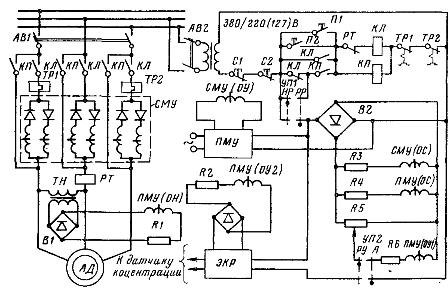
Rice. 4. Diagram of the electric drive of the evaporator pump.
In order to obtain sufficiently rigid mechanical characteristics of the electric drive, in addition to the internal positive current coupling created by the working windings of the SMU, a negative voltage coupling is applied. The use of the PMU makes it possible to increase the output power of the EKR to the degree necessary to control the SMU, as well as to reduce the size of the voltage transformer VT and increase the rigidity of the mechanical characteristics. To increase engine torque during starting, the magnetic power amplifier is moved by the gearbox contactor.
The engine control circuit allows starting and stopping the pump from the main control panel and from the place of its installation (buttons P1, P2, C1, C2). Switch UP1 allows you to set an unregulated mode of operation of the HP pump when the SMU remains surrounded by the contactor KP, and the pump develops maximum performance, as well as adjustable mode PP, when KP at the end of the start-up is turned off by the current relay RT and the working windings of the SMU are introduced into the stator circuit. Using the UP2 switch, you can select one of the pump's adjustable operating modes: automatic A or manual control of the RU.