Electric circuits of electric drives of overhead cranes operated from the floor
Faucet diagrams and protective features
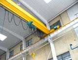 In industry, during low-intensity transport and storage operations, in machine rooms and laboratory rooms, a large number of overhead cranes are used, operating either sporadically or with a number of lifting cycles of 6 - 10 per hour. It is economically impractical to use full-time operators for such cranes. This is why an increasing number of overhead cranes are operated from the floor.
A feature of bridge cranes controlled from the floor is the possibility of access to the crane for repair and control only in specially designated places equipped with suitable areas for checking mechanisms and electrical equipment. Therefore, the entire electrical equipment protection system of the crane must be constructed in such a way that the crane under emergency conditions can be brought to the repair area under control from the floor and in the absence of a crane in the circuit short circuits and ground faults.
In this regard, on floor-operated cranes, circuit breakers are not installed.The main circuits are protected by an automatic power switch basic cartsand protection of control circuits — fuses for currents 15 A, 380 V with a cross-section of conductors of control circuits 2.5 mm2. Overload protection of electric drives of mechanisms is carried out thermal relays in the main circuits of the engines.
To enable the faucet to move after the thermal protection is triggered, the relay contacts are connected to a button on the control panel. The valve is equipped with signal lamps for the presence of voltage at the input, voltage after the contactor for line protection and a signal lamp for the operation of thermal protection.
Electrical diagrams of mechanisms for movement of overhead cranes
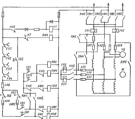
In fig. 1 shows a diagram of an electric drive in motion under short-circuit control of a single-speed motor.
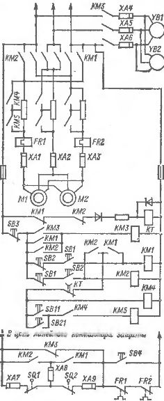
Rice. 1. Scheme of electric drive (with a single-speed squirrel-cage motor) of the crane movement mechanism when operated from the floor: M1, M2 — electric motors, YB1, YB2 — electromagnets of brakes or electrohydraulic pushers, KM1, KM2 — directional contactors, KM4, KM5 — resistor contactors in the circuit stators, KMZ — brake contactor, KT — start-up time relay, FR1, FR2 — thermal relays, SQ1, SQ2 — limit switches, SB1, SB2 — movement direction buttons (two - way), SB11, SB21 — start buttons, SB3 — free movement stop button, SB4 — thermal protection bypass button, XA1 — XA9 — contacts of current transfer carts
This circuit is designed to drive bogie cranes with a load capacity of 3-20 tons and crane drives for cranes with a load capacity of 2-5 tons. The stator windings of a squirrel-cage motor are fed from the mains through two stages of resistors. The mechanical characteristics of the drive are shown in Fig. 2, a.
Control of electric drive — from suspended buttons. The control includes two main two-way buttons SB1 and SB2, which give a command to move in two directions. The transition to a position without adjusting resistors is carried out when commands are issued using the buttons SB11, SB21.
When the engine is turned on, power to the YB brake drive is supplied through the contacts of the contactors KM1, KM2 through the contacts of KMZ. After turning off the electric motor, the brake drive continues to receive power and the mechanism has a free run. To release the brake, use the SB3 button, which is common to the bogie and the axle mechanism. When triggered limit switches SQ1 and SQ2, the protective line contactor is tripped and superimposed mechanical brake.
To provide electricity opposite braking after free boot is used time relay CT with a time delay of 2-3 s, which slows the drive to a position with minimum starting (braking) torque.
In fig. 3 shows a diagram of an electric drive for the movement of an overhead crane (trolley) with the help two-speed squirrel-cage motors… The motor has two separate windings with a pole ratio


The SB1 or SB2 button includes the directional contactors KM1, KM2 as well as the low speed contactor KM4. After supplying power to the low-speed winding of the motor through the contactor KMZ, the brake actuator YB1, YB2 receives power.To switch to high speed, two-way buttons SB close contacts SB11, SB21 (second position) and turn on contactor KM6.
The high-speed coil is connected to the grid through a resistor at the same time as the low-speed coil. The low speed coil is then turned off. After the time delay of the KT relay (2-5 s), the contactor KM5 turns on and the motor reaches its natural characteristic of the high-speed mode (Fig. 2, b).
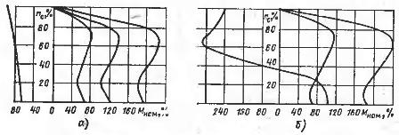
Rice. 2. Mechanical characteristics of diagrams fig. 13
When the motor is disconnected from the mains, the brake actuator continues to receive power and coasting occurs. Electric braking can be applied when changing from high speed to low speed. To release the brake, simply press the SB3 button.
When the last defense is triggered by opening line contactor on protection panel the electric motor is switched off and the mechanical brake is engaged. The mechanism is inhibited with maximum intensity.
Due to the use of resistors in the circuit for high-speed windings, a relatively soft start is performed under the control of the time relay KT, but the braking torque of the low-speed winding is not limited, and in this case, soft braking can be achieved by several pulse switches of the SB1 or SB2 button.
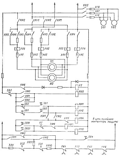
Rice. 3. Diagram of the electric drive (with two-speed squirrel-cage motor) of the crane movement mechanism when operated from the floor: M1.M2 - electric motors, YB1, YB2 - brake drives, KM1, KM 12 - contactors for the direction of travel, KMZ - brake contactor, KM4 - low speed contactor, KM5 - high speed contactor, KM6 - resistor contactor in the stator circuit, FRI, FR2 , FR3 — thermal relays, KT — run control time relay, SQ1, SQ2 — limit switches, SB1, SB2 — travel direction buttons (bidirectional): SB11, SB21 — high speed buttons (second button position SB1, SB2), СВЗ — release of the free stop button, SB4 — thermal protection bypass button, ХА1- ~ ХЛ11 — contacts of current transmission trolleys.
In fig. 4 shows a diagram of the travel mechanism of an overhead crane using a two-speed motor without free drain. The circuit differs from the one considered by the sequential inclusion of low-speed and high-speed windings and a certain limitation of braking torque when the windings are connected in series. The scheme is recommended for overhead cranes operating outdoors.
Diagrams of connection of lifting mechanisms of cranes
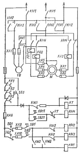
In fig. 5 shows a control circuit for an electric hoist drive using a two-speed squirrel-cage motor with two independent windings with a pole count ratio of 4/24 and 6/16. The circuit is built on the principle of double breaking from two independent devices of the main circuit of the windings of the electric motor and the circuits of the brake drive, which provides the necessary reliability of the hoist drive.
The low-speed winding of the electric motor receives power through the contacts of the line contactor KM1, the contacts of the direction contactors KM2, KMZ and the interrupting contacts of the contactor KM4 after pressing the corresponding button SB1, SB2 (first position).
Rice. 4. Scheme of the electric drive (with a two-speed squirrel-cage motor) of the crane movement mechanism: M — electric motor, YB — brake drive, KM1, KM2 — contactors for the direction of movement, KMZ — low-speed contactor, KM4 — high-speed contactor , KM5 — High Speed Resistor Contactor, CT — Start Time Control Relay, FR4 — Thermal Relays, SQ1, SQ2 — Limit Switches, SB1, SB2 — Travel Direction Buttons, SB11, SB21 — High Speed Buttons, SB3 — Bypass Thermal Relay button, XA1 -XA10 — current transfer contacts
When the SB11 (SB21) button is pressed, the coil of the contactor KM4 receives power, it switches from low speed to high speed with minimal power interruption. In this case, there can be no position when the high-speed and low-speed coils are disabled. The transition from a low-speed winding to a high-speed winding is carried out under the control of the time relay KT. When the limit protection is activated, the motor windings and the brake are activated twice.
In fig. 6 shows a diagram of the electric drive of the lifting mechanism with two short-circuited electric motors connected to each other and to the gearbox through a planetary gear with a gear ratio of 6-8. The low-speed electric motor M2 is turned on during the entire time of operation of the mechanism. The high-speed motor is engaged during high-speed operation.The low-speed electric motor has a built-in brake.
Rice. 5. Scheme of the electric drive (with a two-speed squirrel-cage motor) of the lifting mechanism when operated from the floor: M — electric motor, YB — brake coil, KM1 — lily contactor, KM2 — KMZ — directional contactors, KM4 — contactor for switching speed, FR1 — FR3 — thermal relay, CT — acceleration control relay, SQ1, SQ2 — limit switches, SB1, SB2 — direction buttons (two-way). SB3 — button for shunting thermal relays, SB11, SB21 — high-speed buttons (second position of buttons SB1, SB2), XA1 — XA10 — contacts of current transfer trolleys.
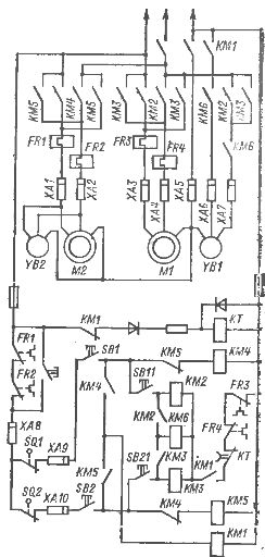
Rice. 6. Scheme of the micromotor of the lifting mechanism when operated from the floor: M1 - high-speed electric motor, M2 - low-speed electric motor, YB1 - high-speed brake coil, YB2 - low-speed motor brake coil, KM1 - linear contactor, KM2 - KMZ - revolutions of high directional contactors, KM4, KM5 - low speed contactors, KM6 - high speed brake contactor, KT - start time control relay, SQ1, SQ2 - limit switches, FR1 - FR4 - thermal relays, SB1, SB2 - two-way direction buttons , SB11, SB21 — high-speed buttons (second position of buttons SB1, SB2), XA1— XA10 — contacts of current transfer carts
The high-speed electric motor has a separate brake operated by electro-hydraulic thruster… When the direction button SB1 (SB2) is pressed, the contactor coil KM4 (KM5) is energized and the low speed motor is turned on. At the same time, the common line contactor KM1 is switched on.
When the button SB1 (SB2) is fully pressed, the contacts SB11 (SB21) are closed, the coil of the contactor KM2 (KMZ) and KM6 is energized, but after the low-speed start time under the control of Relay KT has expired, the high-speed motor is turned on .
When decelerating ascent or descent after the high-speed motor is turned off, braking to a low speed is performed by the YB1 brake. After actuation of the limit switches SQ1 and SQ2, the electric drive is switched off with a double open circuit of the motor and brake drives.
All described schemes, in accordance with the provision for activating the crane mechanisms when working from the floor, only with a constant push of the button. When any type of protection is turned off, the mechanism stops, regardless of the state of the button control device.
The considered schemes in fig. 2-5 can be assembled from standard magnetic starters type PMA, PML and time relay. An exception is the diagram in fig. 2 in which a contactor is used to switch the revolutions dc contactor MK1-22, 40 A, 380 V, coil 220 V. According to the indicated schemes, control panels for motors with a power of 0.8 to 2×8.5 kW and control panels for lifting motors with a power of 10 to 22 kW have been developed .