Electric drives with asynchronous phase motors and coupling braking
 Until recently, electric drives with asynchronous phase motors, due to their simplicity of implementation, were the most widely used for crane electric drives, especially for travel mechanisms. In the lifting mechanisms these electric drives are increasingly being replaced by self-excited dynamic braking systems. Full electric drives are made based on the use of phase rotor asynchronous crane motors when controlled by KKT60 power regulators and control panels TA, DTA, TCA, K, DK, KS.
Electric actuators with feed cam controllers and TA, DTA (for travel mechanisms) and TCA (for lifting mechanisms) panels with AC control circuits are used for general purpose cranes, and with K, DK (motion) and KS panels (lifting) — with direct current control circuits for metallurgical cranes.
The specifics of use also determine some differences in the construction of these panels.K and KS panels have individual protection, while for TA and TCA panels the main circuit is with common protection placed on a separate protection panel, in DC panels for two- and multi-motor electric drives, separation of motor power circuits is provided to increase reliability of the system, there are other differences.
The power range covered by the electric drives and feed cam controllers is from 1.7 to 30 kW and increases to 45 kW with the addition of a contactor reverser and with control panels from 3.5 to 100 kW for motion mechanisms and from 11 to 180 kW for lifting mechanisms (powers are specified for 4M operating mode with duty cycle = 40%).
The speed control methods and braking modes used in the considered electric drives determine their low control and energy properties. A characteristic feature of such systems is the lack of stable landing and intermediate speeds and large losses in the starting resistors. In general, the control range of these electric drives does not exceed 3:1, and the equivalent efficiency for 4M mode is about 65%.
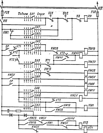
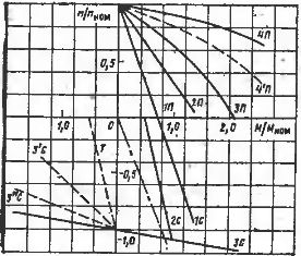
Electric drive schemes for lifting mechanisms. The scheme of the electric drive with the cam controller KKT61 is shown in fig. 1. Close to it in the design is the electric drive circuit with the KKT68 controller, in which a contactor reverser is used in the stator circuit, and the released contacts of the controller are used to parallel connect the resistances in the rotor circuit. The mechanical characteristics of an electric actuator with cam controllers are shown in Fig. 2.
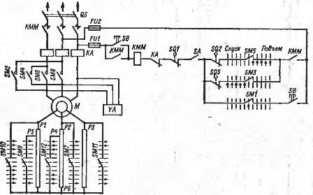
Rice. 1. Diagram of the electric lift drive with cam controller KKT61
When constructing the mechanical characteristics of the considered electric drives, an important issue is the choice of the value of the initial starting torque (characteristics 1 and 1 ') On the one hand, from the point of view of reducing the impulse moment during acceleration and ensuring landing speeds during lowering on light loads, it is desirable to reduce the starting torque. On the other hand, excessive reduction of the initial torque can cause heavy loads to drop into the lifting positions and excessive speeds occur when lowering them. To avoid this, the starting torque should be around 0.7 Mnom.
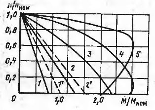
Rice. 2. Mechanical characteristics of the electric drive according to the diagram in fig. 1
In fig. 2, motor torque at duty cycle = 40% is taken as nominal. Then in the duty cycle = 25% of the first position of the controller, characteristic 1 'will correspond to the initial torque equal to Mn at duty cycle = 40%. respectively the second position — characteristic 2 '. To ensure this, the ballast resistors have taps that allow some of the final stage resistance to be bypassed.
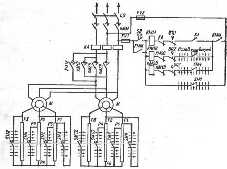
Rice. 3. Diagram of the drive of an electric lift with the TCA panel.
In the diagram of fig. 1 contacts SM2, SM4, SM6 and SM8 of the controller perform motor reversal, contacts SM7 and SM9 — resistor steps of SM12, contacts SM1, SM3 and SM5 are used in protective circuits. Brake coil YA is activated simultaneously with the motor. In the circuit with the KKT61 controller, in order to reduce the number of cams used, an asymmetric connection of resistors is used, and in the circuit with the KKT68, the number of contacts of the controller allows symmetrical switching.
The electric drive is protected by a protection panel that contains the line contactor KMM, the power switch QS, the fuses FU1, FU2 and the maximum relay block KA. Final protection is provided by switches SQ2 and SQ3. The KMM contactor coil diagram includes the SB ON button contacts, the SA emergency switch and the SQL hatch interlock contacts.
In fig. 3 shows a drive diagram of electric hoists with a TCA control panel. Electric drives with KS panels are built on the same principles. The differences are that in them the control circuit is made on direct current, and the protective devices, including the line contactor KMM, the circuit breaker QS1, the maximum relays KA, the fuses FU1 and FU2 are located directly on the panel, and the protection is individual, and in electric drives with panels TCA uses a security panel.
It should be noted that for critical electric drives, a modification of AC control panels of the TSAZ type has also been produced. Electric drive circuits with control panels provide automatic start, reverse, stop and step speed control based on the characteristics of the motor rheostat.
In the diagram of fig. 3 accepted designations: KMM — linear contactor; KM1V and KM2V — directional contactors; KM1 — brake contactor YA; KM1V — KM4V — acceleration contactors; KM5V — opposition contactor. The protection affects the KH relay.
The mechanical characteristics of the drive are shown in Fig. 4. In the lifting positions, the start is carried out under the control of the time relays KT1 and KT2, while the characteristic 4'P is not fixed.In the lowering positions, the adjustment of the characteristics of the opposition 1C and 2C and the characteristic of ZS is carried out, on which, depending on the weight of the load, the engine operates in the mode of power lowering or generator braking. The transition to the 3C characteristics is carried out according to the 3C and 3C characteristics under the control of the time relay.
Rice. 4. Mechanical characteristics of the electric drive according to the diagram in fig. 3.
Panel circuits manufactured before 1979 used a single-phase shutdown mode to step down small loads, accomplished by means of additional contactors. This mode in fig. 4 corresponds to characteristic O. After mastering the dynamic stop panels discussed below, this mode is turned off in the TCA and KS panels. To reduce the load on the opposition characteristics 1C and 2C, the operator must press the SP pedal when the controller handle is placed in the appropriate position. Pedal control is forced with soft mechanical characteristics due to the ability to raise the load instead of lowering it.
Rice. 5. Scheme of two-motor electric drive of the motion mechanism with cam controller KKT62
The electric drive is switched to countershift mode not only when lowering loads, but also when stopping from the lowering positions, and in the first and second positions this is done by pressing the pedal. At the same time, during the holding of the KT2 relay, along with mechanical braking, electrical braking is also provided at characteristic 2C. In addition to the specified relay, KT2 also controls the correct assembly of the circuit.In the circuit of the TCA panels, the braking coil YA is connected to the AC network through the contactor KM1. Both AC and DC braking magnets can be used in KS panels. In the latter case the brake is applied as shown below when looking at the DC panels.
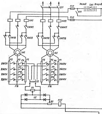
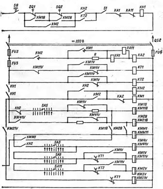
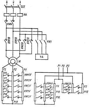
Rice. 6. Schematic of the two-motor electric drive of the movement mechanism with the DK panel
In the diagram of fig. 3, together with the usual connection of resistors, their parallel connection is also shown, which is used in cases where the load exceeds the permissible for the rotor contactors.
Schemes of electrical drives of movement mechanisms. The schemes of electric drives of motion mechanisms with cam controllers are implemented in a single- or dual-motor design. The single motor design with the KKT61 controller is completely similar to the diagram in fig. 1. A diagram of a two-motor electric drive with a KKT62 controller is shown in fig. 5.
The principles of operation of the circuits with the KKT6I and KKT62 controllers are the same: the contacts of the SM controller adjust the resistances in the motor rotor circuit, the protection is placed on a separate protective panel. The difference is that in the circuit with KKT62 the opposite is done by contactors KM1B and KM2V. The mechanical characteristics of both electric drives are identical and are shown in fig. 2.
The scheme of the electric drive of the movement mechanism with control from the panel is considered on the example of a two-motor electric drive with a DK panel with a crane-metallurgical design, shown in Fig. 6. The chain provides the symmetrical mechanical characteristics shown in fig. 7.In the diagram: KMM1 and KMMU11 — linear contactors; KM1V, KM11V, KM2V, KM21V — directional contactors; KM1V — KM4V, KM11V — KM41V — accelerator contactors; Brake contactors KM1, KM2 — YA1 and YA11. The control is carried out by the controller (contacts SA1 — SA11) with the provision of a soft start under the control of the time relays KT1 and KT2.
For stopping, the counter-switching mode is used according to characteristic 1, which is carried out under the control of relay KH2. The relay coil KH2 is connected to the voltage difference proportional to the rotor voltage of one of the motors, rectified by the diode bridge UZ, and the reference voltage of the network. By adjusting potentiometers R1 and R2, the motor decelerates at characteristic 1 to zero speed, after which the motor is allowed to start in the reverse direction. The circuit provides all the necessary types of protection implemented on the voltage relay KN1. The control circuit is powered by a 220 V DC network through the switch QS2 and fuses FU8 — FU4.
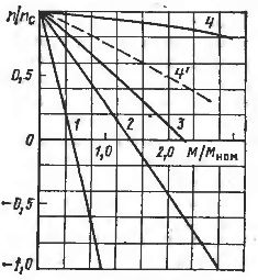
Rice. 7. Mechanical characteristics of the electric drive according to the diagram in fig. 6
Technical data for complete electric drives. Technical data for electric drives of lifting and traveling mechanisms are presented in reference tables. The specified tables determine the power of the motor loads controlled by the power controllers and panels, depending on the mode of operation. The technical data in the tables refer to motors and control panels with a nominal supply voltage of 380 V.
For other voltages it is necessary to use the manufacturer's information materials. For duplex panels, the motor readings shown in the tables are doubled.The TCA3400 and KC400 panels are currently out of production, but electric drives with these panels are still in service. For 6M operating mode, only K, DK and KS panels should be used.