Thyristor voltage regulators
 Thyristor voltage regulators are devices designed to control the speed and torque of electric motors. Regulation of speed and torque is carried out by changing the voltage supplied to the stator of the motor and is carried out by changing the opening angle of the thyristors. This method of motor control is called phase control. This method is a type of parametric (amplitude) control.
Thyristor voltage regulators can be implemented with both closed and open control systems. Open loop regulators do not provide satisfactory speed control performance. Their main purpose is to adjust the torque to obtain the desired operating mode of the drive in dynamic processes.
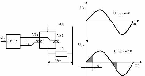
A simplified scheme of a thyristor voltage regulator
The power section of the single-phase thyristor voltage regulator includes two controlled thyristors that ensure the flow of electric current on the load in two directions at a sinusoidal input voltage.
Closed-loop thyristor controllers are used, as a rule, with negative speed feedback, which makes it possible to have sufficiently rigid mechanical characteristics of the drive in the area of low rotational speeds.
The most effective use of thyristor regulators for speed and torque control asynchronous rotor motors.
Supply circuits of thyristor regulators
In fig. 1, a-e show possible schemes for including the rectifier elements of the regulator in one phase. The most common of them is the diagram in fig. 1, a. It can be used for any connection scheme of the stator windings. The allowable current through the load (rms value) in this circuit in continuous current mode is:

where Azt is the permissible average value of the current through the thyristor.
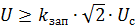
Maximum forward and reverse thyristor voltage

where kzap — safety factor chosen taking into account possible switching overvoltages in the circuit; — the effective value of the line voltage of the network.
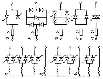
Rice. 1. Schemes of power circuits of thyristor voltage regulators.
In the diagram of fig. 1b, there is only one thyristor included in the diagonal of the bridge of uncontrolled diodes. The ratio between the load and thyristor currents for this circuit is:

Uncontrolled diodes are selected for a current that is half that of a thyristor. Maximum forward voltage to the thyristor
The reverse voltage of the thyristor is close to zero.
The diagram in fig. 1b has some differences from the scheme of fig. 1, but for the construction of the management system. In the diagram of fig. 1, and the control pulses for each of the thyristors must follow the frequency of the power supply. In the diagram of fig.1b, the frequency of the control pulses is twice as high.
The diagram in fig. 1, c, consisting of two thyristors and two diodes, if possible, control, load, current and maximum forward voltage of the thyristors is similar to the diagram in fig. 1, a.
The reverse voltage in this circuit due to the shunting action of the diode is close to zero.
The diagram in fig. 1d in terms of current and maximum forward and reverse voltage of the thyristors is similar to the circuit of fig. 1, a. The diagram in fig. 1, d differs from the considered requirements for the control system to provide the necessary range of variation of the thyristor control angle. If the angle is counted from the zero phase voltage, then for the circuits in fig. 1, a-c, the relation

where φ- phase angle of the load.
For the circuit of Fig. 1, d, a similar ratio takes the form:

The need to increase the range of angle change complicates thyristor control system… The diagram in fig. 1, d can be applied when the stator windings are connected in a star without a neutral conductor and in a delta with the rectifiers included in the line conductors. The scope of this scheme is limited to irreversible as well as reversible electric drives with reverse contact.
The diagram in fig. 4-1, e in its properties is similar to the scheme in fig. 1, a. The triac current here is equal to the load current, and the frequency of the control pulses is equal to twice the frequency of the supply voltage. The disadvantage of a triac circuit is much smaller than that of conventional thyristors, the allowable values du / dt and di / dt.
For thyristor regulators, the most rational scheme is in fig. 1, but with two anti-parallel connected thyristors.
The power circuits of the regulators are implemented with anti-parallel thyristors in all three phases (symmetrical three-phase circuit), in two and one phase of the motor, as shown in fig. 1, f, g and h respectively.
In regulators used in crane electric drives, the most widespread is the symmetrical switching circuit shown in fig. 1, e, which is characterized by the lowest losses from higher harmonic currents. The larger losses in circuits with four and two thyristors are determined by the voltage imbalance in the motor phases.
Basic technical data for PCT series thyristor regulators
Thyristor regulators of the PCT series are devices for changing (according to a given law) the voltage supplied to the stator of an induction motor with a wound rotor. Thyristor controllers of the PCT series are made according to a symmetrical three-phase switching circuit (Fig. 1, e). The use of regulators of the specified series in crane electric drives allows regulation of the rotation frequency in the 10: 1 range and regulation of the engine torque in dynamic modes during start-up and stop.
Thyristor regulators of the PCT series are designed for continuous currents of 100, 160 and 320 A (maximum currents of 200, 320 and 640 A respectively) and voltages of 220 and 380 V AC. The regulator consists of three power supply units assembled on a common frame (according to the number of phases of anti-parallel connected thyristors), a current sensor unit and an automation unit. The power supplies use tablet thyristors with extruded aluminum profile coolers. Air cooling — naturally. The automation block is the same for all versions of the regulators.
The thyristor regulators are manufactured with an IP00 degree of protection and are intended for mounting on standard TTZ type magnetic controller frames, which are similar in design to TA and TCA series controllers. The overall dimensions and weight of the PCT series regulators are shown in the table. 1.
Table 1 Overall dimensions and weight of PCT series voltage regulators

TTZ magnetic controllers are equipped with directional contactors for reversing the motor, contactors of the rotor circuit and other relay-contact elements of the electric drive, which communicate the controller with the thyristor regulator. The construction structure of the regulator control system is visible from the functional diagram of the electric drive shown in Fig. 2.
The three-phase symmetrical thyristor block T is controlled by the SFU phase control system. Using the controller KK in the regulator, the speed setting of BZS is changed. Through the block BZS, in the function of time, the accelerator KU2 in the rotor circuit is controlled. The difference between the reference signals and the TG tachogenerator is amplified by the amplifiers U1 and UZ. A logic relay device is connected to the output of the amplifier UZ, which has two stable states: one corresponds to the switching on of the forward direction contactor KB, the second - to switching on of the forward contactor backward direction KN.
Simultaneously with a change in the state of the logic device, the signal in the control circuit of the switchgear is reversed. The signal from the matching amplifier U2 is summed with the motor stator current delayed feedback signal that comes from the current limiting block TO and fed to the input of the SFU.
The logic block BL is also affected by the signal from the current sensor DT and the current presence module NT, which prohibits the switching of the directional contactors while energized. The BL unit also performs nonlinear correction of the speed stabilization system to ensure the stability of the drive. Regulators can be used in electric drives of lifting and traveling mechanisms.
The PCT series regulators are made with a current limiting system. The level of current limitation for protection of thyristors from overload and for limiting the motor torque in dynamic modes varies smoothly from 0.65 to 1.5 of the rated current of the regulator, the level of current limitation for protection against overcurrent — from 0 ,9 to. 2.0 rated current of the regulator. A wide range of protection settings allows the operation of a regulator of the same standard size with motors that differ in power by a factor of about 2.
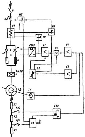
Rice. 2. Functional diagram of an electric drive with PCT type thyristor regulator: KK — command controller; TG — tachogenerator; KN, KB — directional contactors; BZS — speed setting block; BL — logical block; U1, U2. US — amplifiers; SFU — phase control system; DT — current sensor; IT — current unit of presence; TO — current limiting unit; MT — protective unit; KU1, KU2 — acceleration contactors; KL — linear contactor: R — circuit breaker.
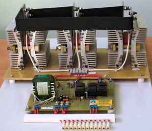
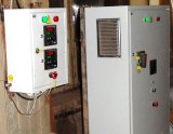
Rice. 3. Thyristor voltage regulator PCT
The sensitivity of the current presence system is 5-10 A rms current in the phase. The regulator also provides protection: zero, from switching overvoltages, from loss of current in at least one of the phases (blocks IT and MT), from interference in radio reception.PNB 5M type high speed fuses provide protection against short circuit currents.