Shaft power of pumps, fans and compressors
 Based on the set supply for the fan or pump and the total head, and for the compressor - supply and specific compression work, the shaft power is determined, according to which the power of the drive motor can be selected.
For a centrifugal fan, for example, the formula for determining shaft power is derived from the expression for the energy transferred to the moving gas per unit time.
Let F be the cross-section of the gas pipeline, m2; m is the mass of gas per second, kg / s; v — gas velocity, m / s; ρ is the gas density, m3; ηc, ηp — fan and transmission efficiency.
It is known that

Then the expression for the energy of the moving gas will take the form:
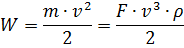
whence the shaft power of the drive motor, kW,
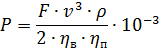
The formula can be divided into groups of quantities corresponding to the flow rate, m3 / s and the fan pressure, Pa:


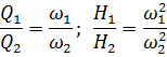
From the above expressions it is seen that


Accordingly
here c, c1 c2 are constants.
Note that due to the presence of static pressure and the design features of centrifugal fans, the degree on the right hand side may differ from 3.
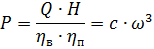
Similar to the way it was done for the fan, it is possible to determine the shaft power of the centrifugal pump, kW, which is equal to:
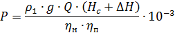
where Q is the flow rate of the pump, m3 / s;
Ng — geodesic head equal to the difference between the discharge and suction heights, m; Hs — total pressure, m; P2 — pressure in the reservoir where the liquid is pumped, Pa; P1 — pressure in the tank from where the liquid is pumped, Pa; ΔH — pressure loss in the line, m; depends on the cross-section of the pipes, the quality of their processing, the curvature of the pipeline sections, etc.; Values of ΔH are given in the reference literature; ρ1 — density of the pumped liquid, kg / m3; g = 9.81 m / s2 — acceleration of gravity; ηn, ηn — pump and transmission efficiency.
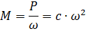
With a certain approximation for centrifugal pumps, it can be assumed that there is a relationship between shaft power and speed P = сω3 and M = сω2... In practice, the speed indicators vary within 2.5-6 for different designs and operating conditions of pumps, which must be taken into account when choosing an electric drive.
The indicated deviations are determined for the pumps by the presence of basic pressure. Let us note by the way that a very important circumstance when choosing an electric drive for pumps operating on a high-pressure line is that they are very sensitive to a decrease in engine speed.
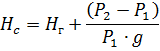
The main characteristic of pumps, fans and compressors is the dependence of the developed head H on the supply of these mechanisms Q. The indicated dependences are usually presented in the form of HQ graphs for various speeds of the mechanism.
In fig.1, as an example, the characteristics (1, 2, 3, 4) of a centrifugal pump are given at different angular velocities of its impeller. In the same coordinate axes, the characteristic of line 6, on which the pump works, is plotted. The line characteristic is the relationship between the supply Q and the pressure required to lift the liquid to a height, overcome the excess pressure at the outlet of the discharge line and the hydraulic resistances. The points of intersection of characteristics 1, 2, 3 with characteristic 6 determine the values of head and capacity when the pump works on a certain line at different speeds.
Rice. 1. Dependence of the pressure H of the pump on its power supply Q.
Example 1. Build the characteristics H, Q of a centrifugal pump for different speeds 0.8ωn; 0.6ωn; 0.4ωn if characteristic 1 is given at ω = ωn (Fig. 1).
1. For the same pump

Therefore,
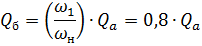
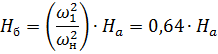
2. Let's build a pump characterized by ω = 0.8ωn.
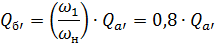
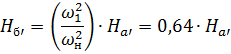
For point b
For point b '
In this way, it is possible to construct auxiliary parabolas 5, 5 ', 5 «..., which degenerate in a straight line along the ordinate at Q = 0 and the characteristics of QH for different pump speeds.
The engine power of a reciprocating compressor can be determined based on the air or gas compression indicator diagram. Such a theoretical diagram is shown in fig. 2. A certain amount of gas is compressed according to the diagram from the initial volume V1 and pressure P1 to the final volume V2 and pressure P2.
Compressing a gas requires work, which will vary depending on the nature of the compression process. This process can be carried out according to the adiabatic law without heat transfer when the tracer diagram is bounded by curve 1 in Fig.2; according to the isothermal law at constant temperature, respectively curve 2 in fig. 2, or along the polytropic curve 3, which is shown by the solid line between the adiabatic and the isotherm.
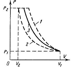
Rice. 2. Gas compression indicator diagram.
The work of gas compression for a polytropic process, J / kg, is expressed by the formula
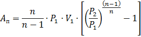
where n is the polytropic index determined by the equation pVn = const; P1 — initial gas pressure, Pa; P2 is the final pressure of the compressed gas, Pa; V1 — initial specific volume of gas or volume of 1 kg of gas at intake, m3.
The motor power of the compressor, kW, is determined by the expression
here Q is the flow rate of the compressor, m3 / s; ηk — compressor efficiency index, taking into account power losses in it during a real work process; ηπ — efficiency of the mechanical transmission between the compressor and the engine. Since the theoretical diagram of the indicator differs significantly from the actual one, and obtaining the latter is not always possible, when determining the power of the compressor shaft, kW, an approximate formula is often used, where the initial data is the work of isothermal and adiabatic compression, as well as efficiency.compressor whose values are given in the reference literature.
This formula looks like this:
where Q is the compressor feed, m3 / s; Au — isothermal work of compression of 1 m3 of atmospheric air to pressure P2, J / m3; Aa — adiabatic work of compression of 1 m3 of atmospheric air to pressure P2, J / m3.
The relationship between the shaft power of a piston type production mechanism and speed is completely different from the corresponding relationship for fan shaft torque mechanisms.If a reciprocating mechanism, such as a pump, operates on a line where a constant head H is maintained, then it is obvious that the piston must overcome a constant average force on each stroke, regardless of the speed of rotation.
Average power value

but since H = const, then

Therefore, the average value of the shaft moment of a reciprocating pump at constant back pressure does not depend on the speed:

The power of the shaft of a centrifugal compressor, as well as of a fan and a pump, subject to the above reserves, is proportional to the third power of the angular velocity.
Based on the obtained formulas, the shaft power of the corresponding mechanism is determined. To select a motor, the nominal values of flow and head must be substituted in the indicated formulas. According to the output power, the continuous duty motor can be selected.