Nodes of automatic control circuits as a function of time
 Electromagnetic, electronic, motor and electropneumatic are widely used in automation circuits. time relay... The most common signal duration conversion schemes are shown in fig. 1. Diagram fig. 1, and provides a pulse of a certain duration, regardless of the duration of pressing buttons SB. After pressing the button SB, relay K is activated, which gives an impulse to turn on the mechanism. The duration of the pulse is determined by the time delay of the KT relay. The SB button can be replaced with a KQ command relay.
Diagrams Fig. 8, b (with electromagnetic time relay) and fig. 1, c (with electropneumatic or motorized time relay) are used to supply a short-term pulse after the start of the action of the travel switch SQ. In these and subsequent schemes, instead of contacts motion switch KQ relay contacts can be used.

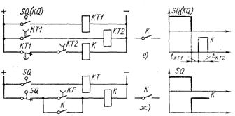
Rice. 1. Circuits for converting the duration of signals
Scheme fig.1d provides a pulse of duration tKT2 with a time delay tKT1 after the start of the action of the switch SQ.
The circuit node Fig. 1, e. If a time delay tKT1 is required before this pulse is applied, the circuit in fig. 1, e. The pulse duration is tKT2.
In positional control circuits, the circuit of Fig. 1g, which performs the function of issuing a long command after the end of the impact on the trip switch SQ. The command is canceled at the start of a new action on the SQ switch.
A short time delay (up to 1.5 s) can be obtained by switching on and off in a conventional way intermediate relays due to the shunting of their coils with capacitors or diodes.
In the diagram of fig. 2, and when contact KQ is closed, relay K is activated with a time delay determined by the charging time of capacitor C. When KQ is closed, relay K also returns with a delay due to the discharge of the capacitor.

Rice. 2. Obtaining time delays by shunting the coils of intermediate relays with capacitors or diodes
To obtain a time delay only when the relay is on, use the circuit in Fig. 2, b. The delay when the relay is turned off is practically absent, since the capacitor quickly discharges to the resistor R (the resistance of the resistor R is significantly less than the resistance of the relay coil K). A similar problem is solved by the circuit in fig. 2c, which uses one opening contact of the KQ relay. The disadvantage of this circuit is the significant loss of energy through the resistor in the absence of a signal.
The scheme in fig. 2d, where when contact KQ opens, relay K turns off with a time delay controlled by resistor R.
According to the diagram in fig. 2, e a time delay is created when K is off after the contact of command relay KQ is closed.
If a slight delay in the return of relay K is required when the command relay KQ is activated, the diagram in fig. 2, e, in which the coil of the relay K is shunted by a diode.
The scheme for generating pulses of a given duration and duty cycle is shown in fig. 3, a. The duration of the pulse is determined by the time delay of the KT2 relay, the pause is determined by the delay time of the KT1 relay.
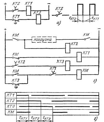
Rice. 3. Relay circuits for generating pulses
In fig. 3, b, a diagram of the periodic switching on of the mechanism with an extended pause time is given. The switch-on time of the contactor KM is equal to the time delay of the relay KT1, the duration of the pause is the sum of the delays of the relay KT2 and KTZ. The timing diagram is shown in Fig. 3, c.
Schematics of pulse generators of time relays or logical elements (see below) are also used to regulate the speed of operation of linear mechanisms. The temperature controller also became widespread, containing a KEP-12U command device, in many ways similar to an engine timing relay. The unit has an executive motor, variable gears, cam drum, switch and 12 contacts.
Speed regulators usually use the scheme for cyclic operation of the KEP-12U device (Fig. 4, a). The circuit is made using the relays K1 and K2 and the contacts of the command device KT.1 and KT.2, the circuit diagram of which is shown in fig. 4, b.
Before starting work, turn on the S switch.When the KQ relay contact is briefly closed, giving a command to start the duty cycle, the K1 relay is energized and self-latching. Relay K2 is activated by switching on the command device KT. Motor windings LM1 and LM2 are energized and the cam drum starts rotating. The output contacts of the device KT.3, KT.4, etc., sequentially closing, at the set moments of time (see the diagram in Fig. 4, b) give commands to turn on the linear mechanisms. In the middle of the cycle, contact KT.1 opens and relay K1 turns off.
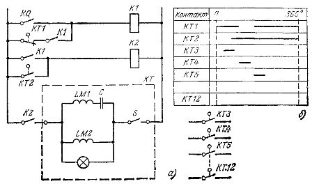
Figure 4. Line speed controller with the KEP-12U device
The relay coil K2 supports the power supply through the contact of the device KT.2. After rotating the drum through an angle of 360 °, the contact KT.2 opens, the motor of the KEP-12U device stops. The chain is ready for the next cycle.
In conclusion, we will consider two schemes for remote control of the delay of electromagnetic time relays.
To change the delay from the control panel, you can use a two-coil relay circuit with trigger coils KT.1 and return coils KT. 2 (demagnetization), whose MDS are directed oppositely (Fig. 5, a). The MDS of the release coil is adjusted using the RP potentiometer. To avoid repeated operation of the CT after the magnetization reversal is returned and tripped, the MDS of the tripping coil must be less than the MDS sufficient to pull the armature, or its own relay closing contact must be introduced in the circuit coil (Fig. 5, a).
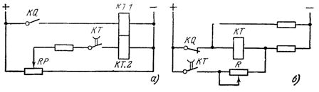
Figure 5. Schematics for remote adjustment of the time relay delay
According to the diagram in fig.5, b make a remote change in the time delay of a single coil relay. When the contact KQ opens, the relay coil KT flows around with a degaussing current which is regulated by resistor R. As the degaussing current increases, the delay of the relay decreases and vice versa. With a supply voltage of 220 V, a relay with a coil for a nominal voltage of 110 V is used.