How to properly connect a welding transformer
Electric welding equipment must be reliably grounded. Transformer housings have special bolts labeled "Earth". In addition, for welding transformers, the terminals of the secondary windings are grounded. Connection diagram of a welding transformer shown in the figure.
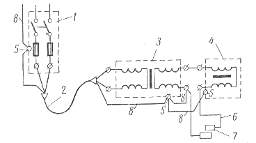
Connection diagram of the welding transformer to the welding station: 1 — welding station, 2 — hose with a three-wire cable with a ground wire, 3 — welding transformer, 4 — regulator, 5 — ground clamps of the housing, 6 — single-wire hose cable, 7 — electrode holder, 8 — ground wires
Before starting at the transformer, it is necessary to check the correspondence of the voltage of its primary winding to the supply voltage of the network. The welding circuit must be open before turning on the transformers.
Transformers must be connected to the mains with separate circuit breakers.
Distance from the grid to welding machine must be the smallest.The cross-sections of the wires connected to the secondary circuits of the transformers or to the terminals of the welding generators are selected according to the table.
Wire cross-section, mm2 The highest permissible current strength, A Wire cross-section, mm2 The highest permissible current strength, A 16 100 70 270 25 140 95 330 35 170 120 380 50 215 150 440
To supply current to the electrode holder, insulated flexible wires in a protective hose with a length of at least 3 m are used. Their cross sections are selected according to the table.
Load rates on flexible welding wires connected to the electrode holder.
The highest permissible current strength, A Wire section, mm2 single double 200 25
300 50 2×16 450 70 2×25 600 95 2×35
Steel bars with a residual cross-section, various steel structures, the welded structure itself, etc. They can serve as a return wire to connect the workpiece to be welded to the welding current source. It is not allowed to use the grounding network as a return conductor, as well as metal structures of buildings, equipment, etc. Mr.
Voltage drop in the supply welding connecting wires is not allowed more than 5% of the mains voltage. If this condition is not met, the cross-section of the wires must be increased.
Useful tips for the operation of welding transformers
 Maintenance of welding transformers is simpler than welding generators and their maintenance is reduced to ensuring reliable earthing of the case, keeping all contacts in good condition and periodically checking the insulation resistance of the windings, especially when the device is operated outdoors.
The following malfunctions may occur during operation in welding transformers:
- strong hum and heating of the windings due to the turn circuit in the primary windings. The damage is eliminated by partially or completely rewinding the coils;
- the transformer produces a very large current due to a short circuit in the secondary winding or in the regulator winding. Eliminate the malfunction by removing the short circuit in the windings or rewinding them;
- the welding current does not decrease when the regulator is exposed, which can be caused by a short circuit between the regulator clamps;
- the regulator hums abnormally during welding, this can happen due to a malfunction of the drive or due to a weakening of the spring tension;
- strong heating of the contacts in the connections due to damage to the electrical contact; the malfunction is eliminated by heating barrier connections, removing and tightly fitting the contact surfaces and tightening the clamps to failure.
See also on this topic: Rules for the operation of welding transformers