Connection diagrams of a magnetic starter for controlling an asynchronous electric motor
Magnetic switch is the simplest set of devices for remote control of electric motors and, in addition to the contactor itself, there is often a button station and protective devices.
Connection diagram of an irreversible magnetic starter
In fig. 1, a, b respectively show the installation and wiring diagrams of an irreversible magnetic starter for controlling an asynchronous electric motor with a squirrel-cage rotor. On the circuit diagram, the boundaries of a device are outlined with a dotted line. It is convenient for hardware installation and troubleshooting. These charts are difficult to read because they contain many intersecting lines.
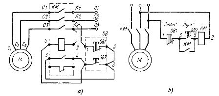
Rice. 1. Circuit diagram for switching on an irreversible magnetic starter: a — circuit diagram for switching on the starter, circuit diagram for switching on the starter
In the schematic diagram, all elements of a magnetic starter have the same alphanumeric designations.This makes it possible to disassociate the conventional images of the contactor coil and the contacts, achieving the greatest simplicity and clarity of the circuit.
A reversible magnetic starter has a KM contactor with three main closing contacts (L1 — C1, L2 — C2, L3 — C3) and one auxiliary closing contact (3-5).
The main circuits through which the motor current flows are usually depicted with bold lines, and the starter coil supply circuits (or control circuit) with the highest current are represented with thin lines.
The principle of operation of the circuit for inclusion of an irreversible magnetic starter
To turn on the electric motor M, you need to briefly press the «Start» button SB2. In this case, a current will flow through the coil circuit of the magnetic starter, the armature will be attracted to the core. This will close the main contacts in the motor power circuit. At the same time, the auxiliary contact 3 — 5 will close, which will create a parallel supply circuit to the coil of the magnetic starter.
If the «Start» button is now released, then the coil of the magnetic starter will be switched on through its own auxiliary contact. This is called a self-locking chain. It provides the so-called zero motor protection. If during the operation of the electric motor the voltage in the network disappears or drops significantly (usually by more than 40% of the nominal value), then the magnetic starter is turned off and its auxiliary contact opens.
After restoring the voltage, to turn on the electric motor, press the «Start» button again. Zero protection prevents the unexpected, spontaneous start of the electric motor, which could lead to an accident.
Manual control devices (knife switches, limit switches) do not have zero protection, therefore control systems using magnetic starters are commonly used in machine drive control systems.
To turn off the electric motor, simply press the "Stop" button SB1. This causes the self-power circuit to open and the magnetic starter coil to break.
Wiring diagram of a reversible magnetic starter
In the event that it is necessary to use two directions of rotation of the electric motor, a reversible magnetic starter is used, the schematic diagram of which is shown in fig. 2, a.
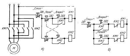
Rice. 2. Schemes for turning on a reversible magnetic starter
The principle of operation of the switching circuits of a reversible magnetic starter
To change the direction of rotation of an induction motor, it is necessary to change the order of phase rotation of the stator winding.
In a reversible magnetic starter, two contactors are used: KM1 and KM2. From the diagram, it can be seen that if both contactors are accidentally switched on at the same time, a short circuit will occur in the main circuit. To exclude this, the circuit is equipped with an interlock.
If, after pressing the SB3 «Forward» button to turn on the KM1 contactor, press the SB2 «Back» button, the open contact of this button will turn off the coil of the KM1 contactor, and the closing contact will energize the coil of the KM2 contactor. The engine will run in reverse.
The electrical diagram of the control circuit of the reversing starter with blocking of auxiliary break contacts is shown in fig. 2, b.
 In this circuit, turning on one of the contactors, for example KM1, causes the coil supply circuit of the other contactor KM2 to open. To reverse, you must first press the «Stop» button SB1 and turn off the contactor KM1. For the reliable operation of the circuit, it is necessary that the main contacts of the contactor KM1 open before the closing of the auxiliary opening contacts in the circuit of the contactor KM2. This is achieved by appropriately adjusting the position of the auxiliary contacts in the direction of the armature.
In series magnetic starters, double blocking according to the above principles is often used. In addition, reversible magnetic starters may have a mechanical interlock with a toggle lever that prevents the contactor solenoids from operating simultaneously. In this case, both contactors must be installed on a common basis.