How to turn on a three-phase electric motor in a single-phase network without rewinding
A three-phase asynchronous motor can be operated from a single-phase network as a single-phase with a starting element or as a single-phase capacitor with a constant-on operating capacity. Using a motor as a capacitor is preferable.
In this case, when the motor is started in operation, to form a rotating magnetic field (in the general case of an elliptical one), coils from all three phases are used, in which, with the help of a three-phase asymmetric system of currents, an active resistance R, an inductance is created L or C capacity.
At the end of the start, in most cases, one of the phases, together with the auxiliary resistance (R, L or C), is disconnected and the motor is transferred to single-phase mode, in which the stator windings create a pulsating, not a rotating magnetic field.
The use of three-phase motors for operation from a single-phase network
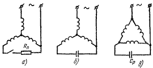
Figures 1 and 2 show different schemes for starting three-phase asynchronous motors when operating from a single-phase network.
 Rice. 1. Connection schemes to a single-phase network of three-phase motors with three terminals:
a — circuit with starting resistance, b, c — circuits with working capacity
If we take the power of a three-phase motor indicated on its panel as 100%, then with a single-phase connection the motor can develop 50-70% of this power, and when used as a capacitor - 70-85% or more. Another advantage of the capacitor motor is that there is no special starting device that is needed in a single-phase circuit to turn off the starting winding after the motor is accelerated.
 Rice. 2. Schemes for connecting three-phase motors with six terminals to a single-phase network:
a — circuit with starting resistance, b, c — circuits with working capacity
The switching circuit in the figures must be selected taking into account the mains voltage and the rated voltage of the motor. For example, with three ends of the stator winding removed (Fig. 1), the motor can be used in a network whose voltage is equal to the rated voltage of the motor.
With six output ends of the winding, the motor has two rated voltages: 127/220 V, 220/380 V. If the mains voltage is equal to the higher rated voltage of the motor, i.e. Uc = 220 V at nominal voltage 127/220 V or UC = 380 V at nominal voltage 220/380 V, etc., then the diagrams shown in fig. 1, a, b. When the mains voltage is less than the rated voltage of the motor, the circuit shown in fig. 1, c. In this case, with a single-phase connection, the power of the motor is significantly reduced, therefore it is recommended to use circuits with working capacity.
Selection of capacitors when connecting three-phase motors to the network
The calculation of the output elements when using three-phase motors as single-phase motors requires knowledge of the parameters of the equivalent circuit of the motor and, being at the same time complicated, does not allow most circuits to accurately determine the required values, therefore, for low-power motors, of in practice, most often the value of starting elements is determined experimentally. The criterion for the correct selection of starting elements is the starting torque and current values.
The operating capacity CP (μF) for each circuit must have a certain value and can be calculated based on the voltage of the single-phase network Uc and the rated current If in the phase of the three-phase motor: Cp = kIf / Uc where k is a coefficient depending on the switching chain. At a frequency of 50 Hz for the circuits in fig. 1, b and 2, b can be taken k = 2800; for the circuit of fig. 1, c — k = 4800; for the circuit of fig. 2, c — k = 1600.
The voltage across the capacitor Uk also depends on the switching circuit and the mains voltage. For the schemes of Figs. 1, b, c, can be taken equal to the mains voltage; for the circuit of fig. 2, b — Uk = 1.15 Uc; for the circuit of fig. 2, e-Uk = 2Uc.
The nominal voltage of the capacitor should be equal to or slightly higher than the calculated value.
It should be remembered that after switching off, capacitors retain the voltage on their terminals for a long time and create a danger of electric shock to a person when touched. The higher the capacitance and the higher the voltage in the capacitor connected to the circuit, the greater the risk of injury. When repairing or troubleshooting the motor, it is necessary to discharge the capacitor after each shutdown.To prevent accidental contact during engine operation, capacitors must be securely fixed and fenced.
The starting resistance Rn is determined empirically using an adjustable resistance (rheostat).
If it is necessary to obtain an increased torque when starting the engine, then the starting capacitor is connected in parallel with the working capacitor. Its capacity is usually calculated by the formula Cn = (from 2.5 to 3) Cp, where Cp is the capacity of the working capacitor. The starting torque is obtained close to the rated torque of the three-phase motor.

