Methods of detecting malfunctions in electrical circuits of electrical equipment of cranes
Fault in electrical circuits of faucets
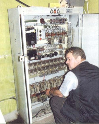
 Electrical equipment of a tower crane consists of a large number electric motors, electrical appliances and devices interconnected by electrical wiring, the length of which reaches several thousand meters. During the operation of the crane, it can damage the electrical circuits. This damage can be caused by damage to elements of machines and devices, breakage, damage to electrical wires and insulation.
Methods of troubleshooting electrical circuits of faucets
Malfunctions electrical circuit are eliminated in two stages. First look for a faulty section of the circuit and then restore it. First -hardest scene. The ability to identify the location of the malfunction in the shortest time and with the lowest labor cost is very important, as it allows a significant reduction in the downtime of the crane. Repairing the damaged area is usually reduced to replacing the defective element (contact, coils, wires) or connecting the broken electrical wiring.
Electrical faults can be divided into four groups: open circuit electrical circuit; short circuit; housing short circuit (insulation damage); the appearance of a bypass circuit when the wires are closed to each other. All these malfunctions can have different external manifestations depending on the functions electrical circuit faucet. Therefore, when troubleshooting, you must carefully analyze the operation of the circuit in all modes, identify deviations in the operation of individual crane mechanisms, and only then proceed to search for malfunctions in the part of the circuit that can cause these deviations.
It is impossible to give a methodology suitable for searching for every case of malfunction, since even the same drive circuits for different crane mechanisms have their own peculiarities. However, some general rules can be used in the analysis of any tap connection scheme.
First, they determine in which circuit—power or control—the fault has occurred.
An example of troubleshooting a faucet electrical circuit
Let's look at an example of a drive circuit malfunction. swinging mechanism of crane C-981A. The malfunction is that the turning mechanism is not included in the left direction. All other mechanisms, including the clockwise rotation mechanism, work.
If during the test, turning the controller handle to the first position Left does not turn on magnetic switch K2 (Figure 1, a), the malfunction follows a search in the control circuit, i.e. in the coil circuit this starter (circuit: wire 27, contact B1-3 of the starter K2 and the jumpers between the main contacts of the starter K2 and starter K1.
 Rice. 1. Locating the location of the fault in the electric circuit of the crane swing drive S-981A;
a — electrical diagram of the swing crane drive; b — circuit diagram of a reversible magnetic starter; /, //, /// ,, IV — the sequence of turning on the voltmeter when checking the circuit
The breaking point can be determined by checking the circuit with a voltmeter or test lamps that turn on as shown in the figure. First, switching on serves to control the operation of the voltmeter itself (control lamp). Let's say that when a voltmeter is connected to terminal 31 it shows voltage (the lamp is on) and when it is connected to terminal 51 it does not show. Therefore, the break located between these terminals. The figure shows that this section includes limit switch VK2 and wires connecting it to the terminals of the control cabinet.
Using this method, to identify the location of the open circuit, it is necessary to strictly follow electrical safety rules: work with dielectric gloves and galoshes or, standing on an insulating stand, do not touch the contacts and bare wires.
When used to test a test lamp, take precautions against turning on the magnetic starter K2 and the tap swing mechanism. To do this, lock the magnetic starter armature in the Off position.In the cold state, the lamp has a small resistance (several times less than a rejection lamp) and when it is connected to terminal 31, a closed circuit (wire 27, control lamp, coil K2, wire 28) that activates the starter K2. When using a voltmeter, the starter does not turn on because the voltmeter coil has a high resistance.
When checking the circuit to determine the location of the break, you must remember that many faucets run part of the circuit on AC and part on DC. On inspection constant current circuit terminals voltmeter (lamp) is connected to a source of direct current, and when checking the circuit of alternating current - to the phase of alternating current. During operation, do not forget to use electrical circuits, since the wrong inclusion of the lamp in the AC phase when testing a DC circuit can damage the rectifiers.
When looking for a case short circuit (insulation failure), the section (with an expected breakdown) is disconnected from the current source, and the voltmeter (lamp) is connected to the current source and the tested area. In normal condition, the disconnected section is isolated from the metal structure of the faucet and a voltmeter (lamp) will not show anything. In case of failure, the voltmeter shows voltage and the lamp lights up. By successively disconnecting individual parts of the tested section of the circuit, you can find the damaged place.
If, for example, in the coil K2 (see Fig. 1) the insulation has broken, then when disconnecting the coil from drive 28 and connecting a voltmeter to terminals 27 and 51 (contact B1-3 of the controller is open), the voltmeter will show voltage.
It is much more efficient and safer to check the circuit using an ohmmeter or probe. The probe consists of a millivoltmeter with a measurement limit of 0-75 mV, connected in series with a resistor R = 40 — 60 Ohm and a battery 4.5 From a pocket flashlight. Probe leads A and B are used to connect to the terminals of the circuit under test. The troubleshooting methodology is similar to the one described above, but the tap is disconnected from the external network, since the ohmmeter and probe have their own current sources.
When using an ohmmeter or a probe, the possibility of an electric shock, in addition, with their help you can find the place of a short circuit in the wires.
Control circuits linear contactor (safety circuits) for faucets of different types executed on the general principle, they differ only in the number of devices in series that are included and have common malfunction symptoms. Each protective circuit can be conditionally divided into three sections: a section with zero contact controllers and a button to turn on the line contactor; blocking zone zero contacts of the controllers and button when the contactor is on and closed block contacts (blocking circuit); common area that includes emergency switches, maximum relay contacts and contactor coil.
An external circuit break sign in each section is a designated line contactor operation sign. When the circuit is broken in the first section, the linear contactor does not turn on when the button is pressed, but turns on when you manually turn the moving part of the contactor until the auxiliary contacts close.When testing the contactor - manually, the following safety measures must be taken: set all controllers to the zero position; turn the movable part of the contactor either using an installer with insulated handles or with dielectric gloves.
If the circuit is open in the second section, the line contactor is energized when the button is pressed, but de-energizes when the button is returned to the normal position.
When the circuit breaks in the third section, the linear contactor it does not turn on either from the button or when you manually move it to the on position.
Malfunctions of electric motors
Of the various causes of malfunction electric motors let's focus on the most common ones.
Short circuit in the rotor winding. Symptom: Turn on the power engine sharp, the engine speed does not depend on the controller position. To check, disconnect the motor rotor from the ballast resistance. If the motor runs when the stator is on, the rotor winding is short-circuited.
Short circuit in the stator winding. Symptom of malfunction: engine does not rotate when switched on, maximum protection is triggered.
Breakage of one of the stator phases when connecting the motor to a star. Signs of malfunctions: the motor does not generate torque and therefore the mechanism does not rotate. To detect a malfunction, disconnect the motor from the mains and check each phase separately with a test lamp. Low voltage (12V) is used for testing. If there is no break, the lamp will turn on and burn at full brightness, and when checking a phase that has an open circuit, the lamp will not burn.
Open circuit in one rotor phase.Symptom of malfunction: the motor rotates at half speed and hums a lot. In case of phase failure of the stator or rotor at engine load and boom winches, the load (boom) can fall regardless of the direction of the controller.