The main types of welding machines
 The fastening of parts by welding and brazing is based on one principle: pouring the elements to be joined with molten metals. Only when soldering, low-melting lead-tin solders are used, and when welding, the same metals from which the welded structures are made.
Physical laws operating in welding
To transfer a metal from a normal solid state to a liquid state, it must be heated to a very high temperature, higher than its melting point. Electric welding machines work on the principle of generating heat in a wire when an electric current passes through it.
In the first half of the 19th century, this phenomenon was described simultaneously by two physicists: the Englishman James Joule and the Russian Emil Lenz. They proved that the amount of heat generated in a conductor is directly proportional to:
1. the product of the square of the passing current;
2. electrical resistance of the circuit;
3. exposure time.
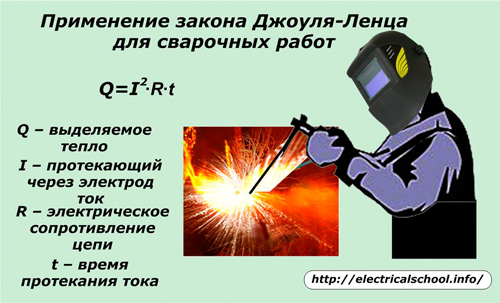
To create the amount of heat capable of melting metal parts with a current, it is necessary to influence it with one of these three criteria (I, R, t).
All welding machines use arc control by changing the value of the current flowing. The remaining two parameters are classified as additional.
Types of current for welding machines
Ideally, a constant time electric current, which can be generated from sources such as rechargeable batteries or chemical batteries or special generators, is best suited to evenly heat the parts and the seam area.
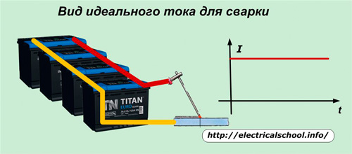
However, the scheme shown in the photo is never used in practice. It has been shown to display a stable current that can strike a smooth, perfect arc.
Electric welding machines operate on alternating current with an industrial frequency of 50 hertz. At the same time, they are all created for long-term, safe work of the welder, which requires the installation of a minimum potential difference between the welded parts.
However, for reliable ignition of the arc, it is necessary to maintain a voltage level of 60 ÷ 70 volts. This value is taken as the starting value for the working circuit while 220 or 380 V is supplied to the input of the welding machine.
Alternating current for welding
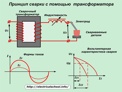
In order to reduce the supply voltage of the electrical installation to the working value of welding, powerful step-down transformers with the ability to adjust the current value are used. At the output, they create the same sinusoidal shape as in the power network. And the harmonic amplitude for arc burning is created much higher.
The design of welding transformers must meet two conditions:
1.limitation of short-circuit currents in the secondary circuit, which, according to the operating conditions, occur quite often;
2. stable burning of the ignited arc necessary for operation.
For this purpose, they are designed with an external volt-ampere characteristic (VAC) that has a steep drop. This is done by increasing the dissipation of electromagnetic energy or by including a choke—a coil of inductive resistance—in the circuit.
In older designs of welding transformers, the method of switching the number of turns in the primary or secondary winding is used to adjust the welding current. This laborious and expensive method has outlived its usefulness and is not used in modern devices.
Initially, the transformer is set to deliver maximum power, which is indicated in the technical documentation and on the nameplate of the box. Then, to adjust the operating current of the arc, it is reduced in one of the following ways:
-
connecting an inductive resistance to the secondary circuit. At the same time, the slope of the I — V characteristic increases and the amplitude of the welding current decreases, as shown in the photo above;
-
change in the state of the magnetic circuit;
-
thyristor circuit.
Methods of adjusting the welding current by introducing inductive resistance in the secondary circuit
Welding transformersthese works on this principle are of two types:
1. with a smooth current control system due to the gradual change of the air gap inside the inductive magnetic wire;
2. with stepwise switching of the number of windings.
In the first method, the inductive magnetic circuit is made of two parts: a stationary one and a movable one, which is moved by the rotation of the control handle.
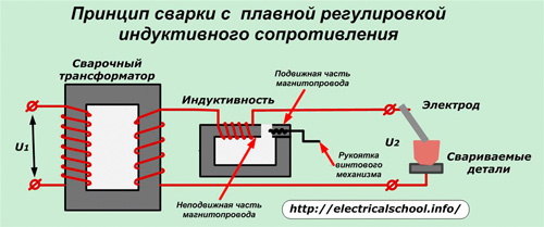
At the maximum air gap, the greatest resistance to the electromagnetic flow and the smallest inductive resistance is created, which provides the maximum value of the welding current.
The full approach of the moving part of the magnetic circuit to the stationary one reduces the welding current to the lowest possible value.
Step regulation is based on the use of a movable contact to switch a certain number of windings in stages.
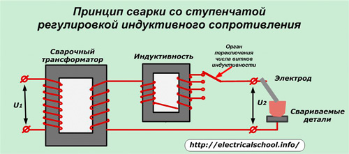
For these inductances, the magnetic circuit is made whole, inseparable, which slightly simplifies the overall design.
A method of current regulation based on changing the geometry of the magnetic circuit of the welding transformer
This technique is performed using one of the following methods:
1. by moving the section of moving coils at a different distance from the stationary mounted coils;
2. By adjusting the position of the magnetic shunt inside the magnetic circuit.
In the first case, the welding transformer is created with increased inductance dissipation due to the possibility of changing the distance between the windings of the primary circuit, stationary in the region of the lower yoke, and the movable secondary winding.
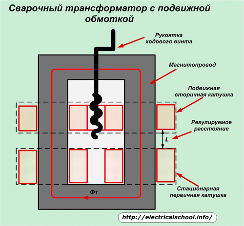
It moves due to manual rotation of the adjusting shaft handle, which works on the principle of a lead screw with a nut. In this case, the position of the power coil is transferred by a simple kinematic diagram to a mechanical indicator, which is graduated in divisions of the welding current. Its accuracy is about 7.5%.For better measurements, a current transformer with an ammeter is built into the secondary circuit.
At the minimum distance between the coils, the highest welding current is generated. To reduce it, it is necessary to move the moving coil to the side.
Such constructions of welding transformers create large radio interference during operation. Therefore, their electrical circuit includes capacitive filters that reduce electromagnetic noise.
How to turn on the movable magnetic shunt
One of the versions of the magnetic circuit of such a transformer is shown in the photo below.
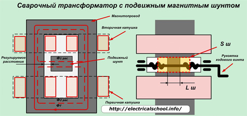
The principle of its operation is based on the maneuvering of a certain part of the magnetic flux in the core due to the inclusion of an adjusting body with a lead screw.
Welding transformers controlled by the described methods are made with magnetic cores made of electrical steel sheets and coils of copper or aluminum wires with heat-resistant insulation. However, for the purpose of long-term operation, they are created with the possibility of good air exchange to remove the generated heat in the surrounding atmosphere, therefore they have a large weight and dimensions.
In all cases considered, the welding current flowing through the electrode has a variable value, which reduces the uniformity and quality of the arc.
Direct current for welding
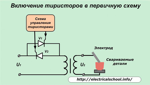
Thyristor circuits
If two oppositely connected thyristors or one triac are connected after the secondary winding of the welding transformer, through the control electrodes, from which the control circuit is used to adjust the opening phase of each half-cycle of the harmonic, then it becomes possible to reduce the maximum current of the power circuit to the value required for specific welding conditions.
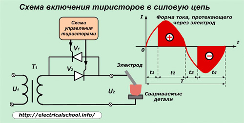
Each thyristor passes only the positive half-wave of the current from the anode to the cathode and blocks the passage of its negative half. Feedback allows you to control both half-waves.
The regulating body in the control circuit sets the time interval t1 during which the thyristor is still closed and does not pass its half-wave. When a current is supplied to the circuit of the control electrode at time t2, the thyristor opens and part of the positive half-wave, marked with a «+» sign, passes through it.
When the sinusoid passes through a zero value, the thyristor closes, it will not pass current through itself until a positive half-wave approaches its anode and the control circuit of the phase-shifting block gives a command to the control electrode.
At the moment t3 and T4, the thyristor connected to the counter works according to the already described algorithm. Thus, in the welding transformer using a thyristor circuit, part of the current energy is interrupted at times t1 and t3 (a pause without current is created), and the currents flowing in the intervals t2 and t4 are used for welding.
Also, these semiconductors can be installed in a primary loop rather than in the electrical circuit. This allows the use of lower power thyristors.But in this case, the transformer will convert the cut parts of the half-waves of the sine wave, marked with the signs «+» and «-«.
The presence of a pause without current during the periods of interruption of a part of the current harmonics is a shortcoming of the circuit, which affects the quality of arc burning. The use of special electrodes and some other measures make it possible to successfully use the thyristor circuit for welding, which has found quite wide application in structures called welding rectifiers.
Diode circuits
Low-power single-phase welding rectifiers have a bridge connection diagram assembled from four diodes.
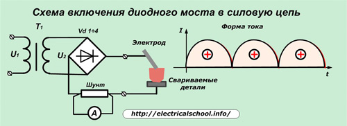
It creates a form of rectified current that takes the form of continuously alternating positive half-waves. In this circuit, the welding current does not change its direction, but only fluctuates in magnitude, creating ripples. This shape maintains the welding arc better than a thyristor shape.
Such devices may have additional windings connected to the operating windings of the current regulating transformer. Its value is determined by an ammeter connected to a rectified circuit through a shunt or sinusoidal — through a current transformer.
Larionov's bridge diagram
It is designed for three-phase systems and works well with welding rectifiers.
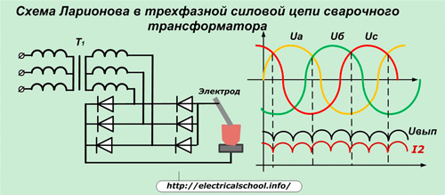
The inclusion of diodes according to the scheme of this bridge makes it possible to add voltage vectors to the load in such a way that they create a final voltage U out, which is characterized by small ripples and, according to Ohm's law, forms an arc current of a similar shape on the welding electrode. It is much closer to the ideal form of direct current.
Features of the use of welding rectifiers
Rectified current in most cases allows:
-
it is safer to ignite the arc;
-
ensures its stable combustion;
-
create less molten metal spatter than welding transformers.
This expands the possibilities of welding, allows you to reliably connect stainless steel alloys and non-ferrous metals.
Inverter current for welding
Welding inverters are devices that perform step-by-step conversion of electricity according to the following algorithm:
1. industrial electricity 220 or 380 volts is changed by a rectifier;
2. the arising technological noises are smoothed out by means of built-in filters;
3. the stabilized energy is inverted into a high-frequency current (10 to 100 kHz);
4. the high-frequency transformer reduces the voltage to the value necessary for stable ignition of the electrode arc (60 V);
5. The high frequency rectifier converts the electricity into direct current for welding.
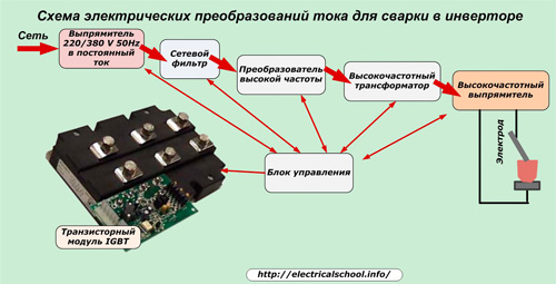
Each of the five stages of the inverter is automatically controlled by a special transistor module of the IGBT series in feedback mode. The control system based on this module belongs to the most complex and expensive element of the welding inverter.
The shape of the rectified current created for the arc by the inverter is practically close to a perfect straight line. It allows you to perform multiple types of welding on different metals.
Thanks to the microprocessor control of the technological processes taking place in the inverter, the work of the welder is greatly facilitated by the introduction of hardware functions:
-
hot start (Hot start mode) by automatically increasing the current at the beginning of welding to facilitate starting the arc;
-
anti-stick (Anti Stick Mode), when when the electrode touches the parts to be welded, the value of the welding current decreases to values that do not cause the metal to melt and stick to the electrode;
-
arc forcing (Arc force mode) when large droplets of molten metal are separated from the electrode when the arc length is shortened and there is a possibility of sticking.
These features allow even beginners to make quality welds. Inverter welding machines work reliably with large fluctuations in the input mains voltage.
Inverter devices require careful handling and protection from dust, which, if applied to electronic components, can disrupt their operation, lead to deterioration of heat dissipation and overheating of the structure.
At low temperatures, condensation may appear on the boards of the modules. This will cause damage and malfunctions. Therefore, inverters are stored in heated rooms and do not work with them during frost or precipitation.