Travel and limit switches
Limit switches, limit switches and micro switches belong to position and position sensors. They are kinematically connected to the working mechanisms and the control drive, depending on the path traveled by the working mechanism. The switch that limits the movement of the operating mechanism is called a limit switch. Limit switches can coordinate the operation of several drives, causing them to start, stop, change speed depending on the position occupied by the mechanism of the working machine.
The principle of operation of the limit switches is not based on the fact that they are mounted on the stationary parts of the working bodies in a certain position, but the moving working bodies to which the cams are attached, reaching a given position, act on the sensors, causing their operation.
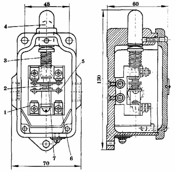
Push motion switch
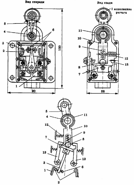
Lever motion switch
Push switches are mainly manufactured with single action.The switch consists of a base 1, a rod 4 lying on the spherical surface of the sleeve 7, fixed contacts 6, carrying a bridge of movable contacts 5. For more reliable switching, movable contacts 5 and fixed 6 are pressed by a spring 2. When applying force the rod 4 moves and the contact bridges are switched, i.e. turn off break contacts and turn on make contacts.
For the torque switches on the terminal bases 1, fixed contacts 2 are fixed. The bridge of movable contacts 6 is mounted on the lever 3. The movable (measuring) lever 5 is not firmly connected to the strap 10, but through a set of band springs 11 (to to avoid damage to the circuit breaker in the event of a spring break) ... The rod 7 is connected to the lever 3. When it is rotated, the ball 8 under the action of the spring 9 forces the rod 7 to immediately switch the contacts at the moment of its release from the lock 13. The contacts return to its original position under the action of plug 4 at any angle within 45° of the axis of the switch.
Purpose and arrangement of limit switches
Many types of limit switches are produced, which differ in the degree of environmental protection (open, dust and splash-proof, waterproof and explosion-proof), in terms of contact opening speed, dimensions, accuracy of operation, design (switches with lever and pulley, with pusher, pin, etc.), the value of the switched current, etc.Limit switches of the following types are most widely used on production mechanisms: crane limit switches KU-700A (KU-701A, KU-703A, KU-704A, KU-70.6A); switches VK-200G, VK-300G; switches of the VPK-1000, VPK-2000, VPK-4000, VP62 series, explosion-proof limit switches VKM-VZG, VPV, etc.
In order to ensure an accurate stop of the mechanism, the limit switch giving the command to decelerate the electric drive must introduce a minimum error caused by the dissipation in the operation of the contacts of the device. The reasons for this error are changes in temperature, humidity, lubrication of rubbing surfaces, etc.
Since accurate braking is usually achieved by pre-shifting the electric motor to a reduced speed, when choosing a limit switch, to avoid delayed opening of the circuit and increase braking accuracy, switches with momentary contact opening should be preferred.
Limit switches VK-200G and VK-300G
 Limit switch VK-300G
Limit switches with instantaneous contact opening VK-200G and VK-300G.
Fixed contacts are mounted in the housing. Movable contacts are attached to the lever. Switching of the contacts is done by turning the actuating lever connected by a set of ribbon springs. When the drive lever is rotated under the action of the spring force transmitted to the ball, the rod, which is firmly connected to the lever, instantly rotates the moment the dog is released. In this case, the switch contacts of the switch.
The contact change time is 0.04 s even at a very low switching speed of 10 mm/min.In all versions of the switches, except for the second, the contacts are returned to their original position by a spring.
The VK-200G Switch has a dust and splash resistant design, and the VK-300G Switch is a waterproof version.
The switches have one marker and one break contact. The switch body can be mounted in any position. The roller arm can be adjusted to any angle. The operating angle of the lever is 12 ± 2 °, the full stroke can be 22 °. The free extra move serves to protect against breakage. The movement speed of the mechanism should not exceed 30 m / min. In the initial position, the lever with the roller is set at an angle of 45 ° to the axis of the switch body at a speed of the mechanism up to 15 m / min and at an angle of 55 ° at a speed of more than 15 m / min.
The inaccuracy of the breaker operation, characterized by the largest deviation of the plate from the middle position at the time of switching, is ± 0.2 mm. The average position of the plate at the moment of actuation of the limit switch is determined as a result of a large number of experiments.
It should be borne in mind that the limit switches VK-200G and VK-300G, made with a conventional roller, are single-action devices (switching is carried out by pressing the switch from one specific side). When the switch fixes not the end, but the intermediate position of the mechanism, and it is possible for the switch plate to move from different sides, it is necessary to install a limit switch with a cut roller.
When the plate moves in the opposite direction, the roller rotates around its axis, and the lever remains stationary: after passing the plate, the roller rotates to its original position under the action of a spring. It is also possible to use a two-roll switch (version 2).
To increase the reliability of the VK-200G and VK-300G switches, it is recommended to manipulate their contacts operating in 110 and 220 V DC inductive circuits with an RC spark arrester circuit. For the circuit. 110 V uses a 0.8 ohm, 5 W resistor and a 0.5 μF, 1000 V capacitor; and in a 220 V circuit — a 1 ohm, 5 W resistor and a 0.25 μF, 1500 V capacitor.
VK-200G and VK-300G switches allow up to 1200 operations per hour.
Limit switches KU-700A
The limit switches of the KU-700A series, originally developed for cranes, have powerful contacts that reliably and with high accuracy interrupt the currents of the contactor coils at sufficiently low revolutions of the mechanisms. They are produced in the following versions: KU-701A, KU-763A, KU-704A and KU-706A.
The maximum speed of the mechanism is 150 m / min for KU-701A, 100 m / min for KU-704A and 300 m / min for KU-706A. For the KU-703A, the maximum speed is not limited.
Switches are used in the control circuits to limit the linear movement of the mechanisms: KU-701A-with small coast values, KU-704A, KU-706A-with any coast, KU-703A limit the travel of the lifting mechanisms.
The body affecting the actuation of the switches is: for KU-701A, KU-706A-the ruler at the limit 70 of the mechanism, for KU-704A-pin, for KU-703A-a shelf mounted on a crane hook traverse that raises or reduces the load on the switch control lever.
The main type is the limit switch KU-701A. Can be mounted in any position; the roller arm can be adjusted to 90 ° and 180 ° from the normal position. Unlike VK-200G and VK-300G, the KU-701A shift lever has three positions, KU-701A is a double-acting device.
 The design of the limit switch KU-701A
The illustration shows a section of the circuit breaker (without the roller control lever). A block of cam elements, a cam drum and a locking device are fixed inside the housing.
The block of cam elements consists of a base on which contact bolts with fixed contacts and two levers with contact bridges are fixed. Lever springs with the help of plates hold the bridge contacts with the bolt contacts in the closed position. When the cam drum rotates, the protrusion of the cam washer is pressed against the protrusion of the lever and the contacts open. The back drum has a shaft on which the drive arm is firmly attached. The back drum has a figured plate (ratchet), which is acted upon by the locking mechanism holding the drum and at the same time the drive in one or another working position.
Investigation of KU-700A series limit switches. showed high accuracy of their work. At movement speeds of the mechanism above 1 m / s, no noticeable errors are observed.
Limit switches VPK-1000, VPK-2000 and VPK-4000
Limit switches of the VPK-1000, VPK-2000 and VPK-4000 series have found application in mechanical engineering. They feature a wide variety of designs. The drive can be made in the form of pusher, pusher with roller, lever with roller, etc.Some types of switches are made with a selective drive that responds to the movement of the switch plate in only one direction.
The VPK-1000 limit switch contains a built-in MP-110 type microswitch and can operate in AC circuits up to 380 V and DC up to 220 V. The switch has one marker and one break contact. The working stroke in the pusher version is 2.4 mm, the additional stroke is 5 mm. In the lever and roller version, these indicators are 15 ± 5 ° and 25 °, respectively. The housing of the switch is protected against dust and splashes of water.
The VPK-2000 series limit switches are direct acting. The actuation error on the movement path of the mechanism at a speed of 20 mm / min is ± 0.3 mm for the version of the drive in the form of a lever with a roller and + 0.1 mm for the version with a pusher. The switch has one marker and one break contact. The case is dustproof, oilproof.
The VPK-4000 series limit switches have up to four contacts in each combination that can operate in AC circuits up to 660 V and DC circuits up to 440 V. The contact system is double open circuit direct acting. The minimum current and voltage at which the contact system works reliably are 0.05 A and 12 V. The operating error on the road is ± 0.1 mm. The body is made in waterproof and other versions.
Explosion-proof limit switches VKM-VZG and VPV
Small explosion-proof limit switches VKM-VZG contain a built-in microswitch with momentary contact opening. The switch is designed to operate in 380 V, 50 Hz and 220 V DC circuits. Nominal current of the contacts 2.5 A.
The driving device is made in the form of a lever, with a roller or pusher.The working stroke of the rod is 1 — 2 mm, the additional stroke after actuation is 4 mm.
The ERW limit switch has a similar design to actuators, containing two to four torque switching contacts. The response time is equal to 0.04 s.
The path errors of the VKM-RZG and VPV limit switches are approximately equal to the errors of the VPK-2000 and VPK-4000 switches.
The described limit switches are widely used. They are simple and inexpensive devices; some of them are quite accurate. However, these devices have a number of significant drawbacks. They are characterized by a relatively low limiting speed of the mechanism, limited service life due to wear of the mechanical part and electrical erosion of the contacts, limited speed and permissible switching frequency. In addition, these devices are sources of noise and radio interference and require periodic adjustment. Therefore, non-contact mechanism position sensors and command devices are increasingly used in mechanism control schemes, but read about this in the next article — Contactless motion switches