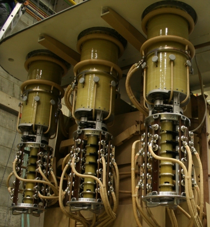
Installation and maintenance of on-load transformer switches
Transformer voltage regulators (unload switch and load switch)
When adjusting the voltage by switching the taps of the transformer windings, they change transformation ratios

where ВБХ AND ВЧХ — the number of HV and LV windings included in the operation, respectively.
This allows maintaining the voltage in the LV (MV) busbars of substations close to the nominal voltage when the primary voltage deviates from the nominal for one reason or another.
Turn on the taps of switched-off transformers on off-circuit tap-changers (non-excitation switching) or on-load transformers on-load tap-changers (on-load regulation).
Almost all transformers are equipped with circuit breaker switches. They allow you to change the degree of transformation in steps within ± 5% of the nominal voltage. Manual three-phase and single-phase switches are used.
On-load switch transformers have a greater number of control steps and a wider adjustment range (up to ± 16%) than on-load switch transformers. Schemes attached voltage regulation of transformers are shown in fig. 1. The part of the HV coil with taps is called the regulating coil.
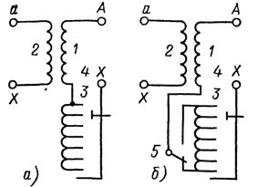
Rice. 1. Schematic of regulation of transformers without reversal (a) and with reversal (b) of the regulating coil: respectively 1, 2 — primary and secondary windings, 3 — regulating coil, 4 — switching device, 5 — reverse
The expansion of the control range without increasing the number of taps is achieved by using reversible circuits (Fig. 1, b). The reversing switch 5 allows you to connect the regulating coil 3 to the main coil 1 in accordance with or vice versa, due to which the range of regulation is doubled. For transformers, on-load switches are usually switched on the neutral side, allowing them to be made with insulation reduced by voltage class.
The voltage regulation of the autotransformers performed on the MV or HV side is shown in fig. 2. In these cases, on-load switches are isolated to the full voltage of the terminal on which side it is installed.
Load switching devices consist of the following main parts: a contactor that opens and closes the operating current circuit during switching, a selector whose contacts open and close an electric circuit without current, an actuator, a current limiting reactor or resistor.
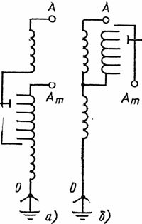
Rice. 2.Autotransformer regulation scheme: a — on the high voltage side, b — on the medium voltage side
The sequence of operation of reactor (RNO, RNT series) and resistor (RNOA, RNTA series) load switches is shown in fig. 3. The necessary consistency in the operation of the contactors and selectors is provided by an actuator with a reversible starter.
In a reactor load switch, the reactor is designed to continuously pass the rated current. In normal operation, only reactive current flows through the reactor. In the process of switching the taps, when it turns out that part of the regulating coil is closed by the reactor (Fig. 3, d), it limits the current I passing in the closed loop to acceptable values.
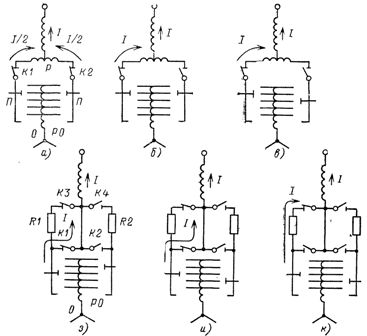
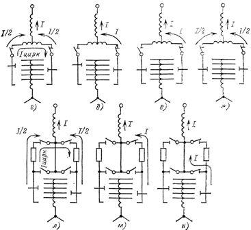
Rice. 3. Sequence of operation of load switches with reactor (ag) and resistor (zn): K1 -K4 — contactors, RO — control coil, R — reactor, R1 and R2 — resistors, P — switches ( selectors)
The non-arcing reactor and selector are usually placed in the transformer tank, and the contactor is placed in a separate oil tank to prevent arcing of the oil in the transformer.
The operation of resistor switches is similar in many ways to that of a reactor load switch. The difference is that in normal operation the resistors are manipulated or turned off and no current flows through them, but during the switching process the current flows for hundredths of a second.
Resistors are not designed for long-term current operation, so the switching of contacts occurs quickly under the influence of powerful springs.Resistors are small in size and are usually a structural part of a contactor.
The on-load tap-changers are controlled remotely from the control panel and automatically from voltage regulating devices. It is possible to switch the actuator using a button located in the actuator cabinet (local control) as well as using a handle. It is not recommended for service personnel to switch the load switch with a live handle.
One cycle of operation of different types of load switches is carried out for a time of 3 to 10 s. The switching process is signaled by a red lamp that lights up at the moment of the pulse and remains on all the time until the mechanism completes the entire switching cycle from one stage to another. Regardless of the duration of a single starting pulse, load switches have an interlock that allows the selector to move only one step. At the end of the movement of the switching mechanism, the remote position indicators complete the movement, showing the number of the stage at which the switch has stopped.
For automatic control, on-load switching devices automatic units for controlling the transformation ratio (ARKT) are offered... The block diagram of the automatic voltage regulator is shown in fig. 4.
The regulated voltage is supplied to the terminals of the ARKT block by a voltage transformer. In addition, the TC current compensation device also accounts for the voltage drop from the load current.At the output of the ARKT device, the executive body I controls the operation of the switch actuator on load. The schemes of automatic voltage regulators are very diverse, but all of them, as a rule, contain the main elements indicated in fig. 4.
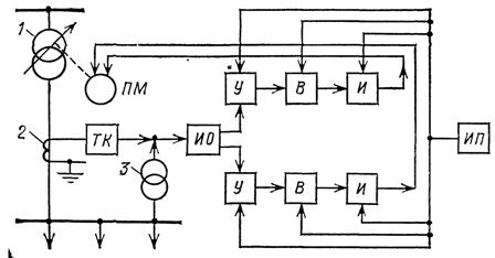
Rice. 4. Block diagram of an automatic voltage regulator: 1 — adjustable transformer, 2 — current transformer, 3 — voltage transformer, TC — current compensation device, IO — measuring body, U — amplifying body, V — retarding body time, I — executive body, IP — power supply, PM — actuator
Maintenance of voltage regulating devices
The rearrangement of circuit breaker switches from one stage to another is rarely carried out in operation - 2-3 times a year (this is the so-called seasonal voltage regulation). During long-term operation without switching, the contact rods and rings of drum-type switches are covered with an oxide film.
In order to destroy this film and create a good contact, it is recommended that each time the switch is moved, it should be pre-rotated (at least 5-10 times) from one end position to another.
When you toggle the switches one by one, check that they are in the same position. Switch drives are secured with locking bolts after translation.
On-load switching devices must always be operated with automatic voltage regulators on.When checking the switch on load, the readings of the position indicators of the switches on the control panel and of the switch actuators of the switch are checked, because for a number of reasons, a mismatch of the selsyn sensor and the selsyn -possible receiver, which is the driver of the position indicators .They also check the same position of load switches of all parallel operating transformers and individual phases with stepwise control.
The presence of oil in the contactor tank is checked by the pressure gauge. The oil level must be maintained within acceptable limits. When the oil level is low, the arcing time of the contacts can be unacceptably long, which is dangerous for the switchgear and transformer. A deviation from the normal oil level is usually observed when the seals of the individual components of the oil system are broken.
The normal operation of the contactors is guaranteed at an oil temperature not lower than -20 ° C. At lower temperatures, the oil thickens strongly and the contactor is subjected to significant mechanical stress, which can lead to its destruction. In addition, resistors can be damaged due to longer switching times and longer power supply. In order to avoid the indicated damage, when the ambient temperature drops to -15 ° C, the automatic heating system of the contactor tank must be turned on.
The load switching drives are the most critical and at the same time the least reliable units of these devices. They must be protected from dust, moisture, transformer oil.The drive cabinet door must be sealed and closed securely.