AC and DC secondary circuit support
Types and purpose of secondary circuits
Secondary circuits are electrical circuits through which the primary circuits (power, that is, the circuits of the main consumers of electricity) are managed and controlled. Secondary circuits include control circuits, including automatic circuits, signal circuits, measurements.
 Secondary circuits with direct and alternating current with a voltage of up to 1000 V are used for power supply and interconnection of devices and devices for control, protection, signaling, blocking, measurement. There are the following main types of secondary circuits:
-
current circuits and voltage circuits, in which measuring devices are installed that measure electrical parameters (current, voltage, power, etc.), as well as relays and other devices;
-
operating circuits that serve to supply direct or alternating current to the executive bodies. These include switching and switching devices installed in the secondary circuits (electromagnets, contactors, circuit breakers, breakers, switches, fuses, test blocks, switches and buttons, etc.).
The current circuits of the measuring currents are mainly used for power supply:
-
measuring devices (indication and recording): ammeters, wattmeters and varmeters, active and reactive energy meters, telemetry devices, oscilloscopes, etc.;
-
relay protection: current organs of maximum, differential, distance, earth fault protection, breaker failure backup devices (CBRO), etc.;
-
automatic closing devices, automatic closing devices of synchronous compensators, power flow control devices, emergency control systems, etc.;
-
some blocking devices, alarms, etc.
In addition, current circuits are used to power AC-to-DC devices used as auxiliary current sources.
When building current circuits, certain rules must be followed.
All devices with a current circuit, depending on their number, length, power consumption and required accuracy, can be connected to one or more current sources.
In multi-winding current transformers, each secondary winding is considered an independent source of current.
The secondaries connected to a single-phase CT are connected to its secondary winding in series and must form a closed loop with the connecting circuits. Opening the circuit of the CT secondary winding in the presence of current in the primary circuit is unacceptable; therefore, circuit breakers, circuit breakers and fuses should not be installed in the secondary current circuits.
To protect personnel in the event of a CT failure (when the insulation between the primary and secondary windings overlaps), a protective ground must be provided in the CT secondary circuits at one point: at the terminal closest to the CT or at the CT clamps.
For protection that combines several sets of CTs, the circuits are also grounded at one point; in this case, grounding through a fuse with a breakdown voltage not exceeding 1000 V and a shunt resistor of 100 Ohm to remove static charge is allowed.
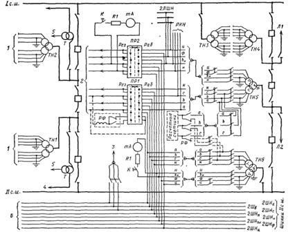
Fig. 1 shows the connection of current circuits to measuring devices and devices for protection and automation and their distribution along the CT for a circuit with three switches for two connections. The characteristic of the first loop is taken into account, which consists in the possibility of feeding each of the two lines from the two bus systems. Therefore, the secondary currents from CTs (eg CT5, CT6, etc.) supplied to the relays and devices on the same primary are summed (except for busbar differential protection and breaker failure protection).
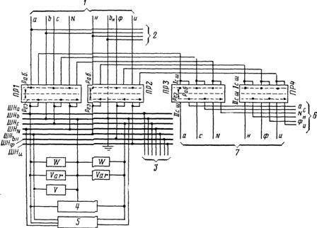
It should be noted that the simplified protective devices shown in the figures, OAPVs, etc., actually consist of several relays and devices connected by electrical circuits. For example, on the line shown in fig. 2, where power flows can change their direction, two meters are connected with plugs for measuring active energy, one of which Wh1 counts the transmitted energy in one direction only, and the other Wh2 - in the opposite direction. Then the secondary current circuits pass through three ammeters, current coils of the wattmeter W and varmeter Var, emergency control devices 1, oscilloscope and telemetry equipment 2.
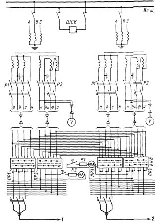
A fixing ammeter FA is connected to the neutral wire, with the help of which the location of the fault along the line is determined. Figure 3 shows bus differential protection current circuits. The secondary current circuits pass through their test blocks, after which the total current of all connections of I or II bus systems (in normal mode, the sum of the secondary currents is zero) through the test block BI1 is fed to the differential protection relay assembly.
In the event that no links are in service (under repair, etc.), the working covers are removed from the relevant test blocks, with the result that the CT secondary circuits are shorted and grounded, and the circuits leading to the protective relay is broken ….
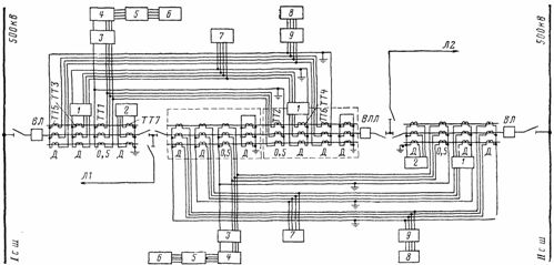
Rice. 1. Scheme of distribution of protections, automation and measuring devices for TT cores for two lines 330 or 500 kV at a substation with a connection diagram «one and a half»: 1 — backup device for failure of circuit breakers and automation for emergency control of lines; 2 — differential bus protection; 3 — counters; 4 — measuring devices (ammeters, wattmeters, varmeters); 5 — automation for emergency control; 6 — telemetry; 7 — backup protection and emergency automation; 8 — basic protection of overhead lines; 9 — single-phase automatic closing (OAPV)
As for test device VI1, in case of deactivation of the differential bus protection — with the working cover removed — all current circuits connected to this busbar system are closed and at the same time the working DC circuits are de-protected ( the latter are not shown in the diagram).
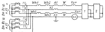
Rice. 2. Circuit diagram for a 330,500 kV line fed by two bus systems: 1 — oscilloscope; 2 — telemetry equipment
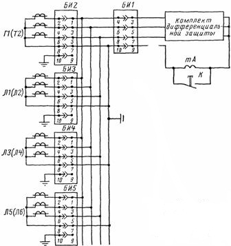
Rice. 3.Circuit diagram of differential protection of 330 or 500 kV buses
The differential protection scheme provides a mA milliammeter connected to the neutral wire of the CT, with the help of which, when the K button is pressed, the operating personnel periodically checks the protection unbalance current, which is very important to prevent its false operation.
Rice. 4. Organization of secondary voltage circuits in open-air 330 or 500 kV switchgears made according to a scheme and a half: 1 — for protection, measuring devices and other devices of the autotransformer; 2 — for protection, measuring devices and other devices from the L2 line; 3 — for protection, measuring devices and other devices from the II bus system; 4 — to RU 110 or 220 kV; 5 — to the backup transformer page 6 or 10 kV; PR1, PR2 — voltage switches; 6 — buses with voltage of the II bus system
Voltage circuits coming from measuring voltage transformers (VT) are mainly used for power supply:
-
measuring devices (indication and recording) — voltmeters, frequency meters, wattmeters, varmeters,
-
active and reactive energy meters, oscilloscopes, telemetry devices, etc.
-
relay protection — distance, direction, voltage increase or decrease, etc.;
-
automatic devices — AR, AVR, ARV, emergency automation, automatic frequency unloading (AFR), frequency control devices, energy flows, blocking devices, etc.;
-
organs for monitoring the presence of voltage. In addition, they are used to power rectifiers used as sources of constant operating current.
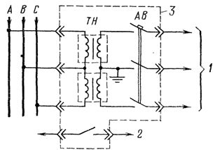
To get an idea of how secondary voltage circuits are formed, see Fig. 4.The figure shows two circuits of one and a half circuits of electrical connections of a 500 kV switchgear: two autotransformers T for communication with a 500 kV switchgear are connected to one and two overhead lines L1 and L2 of 500 kV are connected to the other. From the figure, it can be seen that in the "one and a half" scheme, VTs are installed on all line connections and autotransformers on both bus systems. Each of the VTs has two secondary windings — the primary and the auxiliary. They have different electrical circuits.
The primary windings are connected in star and are used to supply protection and measurement circuits. Additional windings are connected in an open delta pattern. They are mainly used to power earth fault protection circuits (due to the presence of zero-sequence voltage 3U0 at the winding terminals).
The circuits from the VT secondary windings are also brought out to the voltage collector buses to which the VT winding circuits are connected, as well as the voltage circuits of various secondaries.
The most branched buses and circuits of secondary voltage are created at VT of the 500 kV buses. From these buses 6, using switches PR1 and PR2, the backup power supply of the protective circuits (in case of failure of the line VT), meters and calculated meters installed on these lines (in the second case, using an RF blocking relay ), has been delivered.
In order to maintain the accuracy of their readings, power to the calculated meters on the lines is provided by their own control cables specially designed for this purpose.Device RKN is connected to terminals n and b and to the secondary winding of the open delta to monitor the integrity of the zero-sequence circuit 3U0. Under normal conditions, the personnel, using the K button, periodically checks the presence of unbalance voltage and the operability of the winding of the open delta of the VT and its circuits using a mA milliammeter.
Voltage control in the main circuits of the windings is also carried out using the relay RKN (in Fig. 4 it is connected to circuits a and c ТН5). The implementation of voltage circuits has some general rules. For example, VTs must be protected against all types of short circuits in the secondary circuits by automatic switches with auxiliary fault signaling contacts. If the secondary circuits are insignificantly branched and the probability of failure in them is small, circuit breakers may not be installed, for example, in the 3U0 circuit of the VT on the RU busbars of 6-10 kV and 6-10 kV GRU.
In networks with a large grounding current in the secondary circuits of the VT windings connected in an open delta, breakers are also not provided. In the event of a fault in such networks, the faulted sections are quickly switched off by the corresponding network protections and the voltage 3U0 accordingly drops rapidly. Therefore, in the circuits, for example, from the terminals n and bn of the TN line and the 500 kV busbars, there are no circuit breakers. In networks with low ground current at VT between terminals n and bp, 3U0 can exist for a long time with a short circuit in the secondary circuits of VT, it can be damaged. That is why it is necessary to install circuit breakers here.
Separate circuit breakers are provided to protect the voltage circuits laid by the unopened triangle vertices (u, f).In addition, it is planned to install knife switches in all secondary circuits of the VT to create a visible gap in them, which is necessary to ensure the safe performance of repair work on the VT (except for the supply of voltage to the secondary windings) of VT from an external source). In a complete switchgear in the VT circuit on RU busbars s.n. 6-10 kV disconnectors are not installed, as a visible gap is provided when the VT trolley is climbed out of the switchgear cabinet.
The secondary windings and the secondary circuits of the VT must have protective earthing. It is done by connecting one of the phase wires or the neutral point of the secondary windings to the earthing device. The grounding of the secondary windings of the VT is carried out at the terminal node closest to the VT or at the terminals of the VT itself.
Switches, circuit breakers and other devices are not installed in the wires of the grounded phase between the secondary winding of the VT and the earthing point of the circuit breaker. The ground terminals of the VT coils are not combined, and the wires of the control cable connected to them are laid to their destination, for example, to their busbars. Ground terminals of different VTs are not combined.
In operation, there may be cases of failure or recall for repair of VTs, the secondary circuits of which are connected to protection, measurement, automation, measuring devices, etc. To prevent disruption of their operation, redundancy is used.
Rice. 5.Scheme of manual switching of the secondary circuits of the VT in the external switchgear, made according to the diagram of the half: 1-supply of the voltage buses from the VT of the line (for example, L1 ); 2 — to the voltage control relay; 3 — circuits for protection, automatic closing and automation for emergency control; 4 — telemetry equipment; 5 — oscilloscope; 6 — to the voltages of the I bus system; 7 — to the voltage poles of the II bus system
In the one-and-a-half scheme (Fig. 5), in the case of VT output from lines, redundancy is carried out by VTs installed on the busbars, using the PR1 switch for circuits coming from the main winding, connected to a star and the PR2 switch for open delta circuits. Using switches PR1 and PR2, the secondary voltage buses of the line are connected to their own VT (working circuit) or to the VT of the first or second bus system (backup circuit). In the latter case, this switching is carried out via switches PRZ and PR4.
A method of redundantly feeding single-line voltage circuits, for example L1 in Fig. 4 (when pulling out the VT for repair), from another line, for example, L2, should not be used, since in the event of a short circuit and interruption of the L2 line, the voltage protection circuits of the L1 line are deprived of power.
Rice. 6. Scheme of manual switching of secondary circuits of VT in distribution devices with two bus systems: 1 — to meters and other devices of the I bus system in the main control; 2 — to measuring devices and other devices of the II bus system in the main control
In schemes with a double bus system, the voltage transformers must be mutually supported (when one of the VTs is out of operation) using switches PR1-PR4 (Fig. 6). To do this, when switching the switch to connect to the bus, the switch SHSV must be turned on. In circuits with two bus systems, when switching connections from one bus system to another, a corresponding automatic switching of voltage circuits is provided.
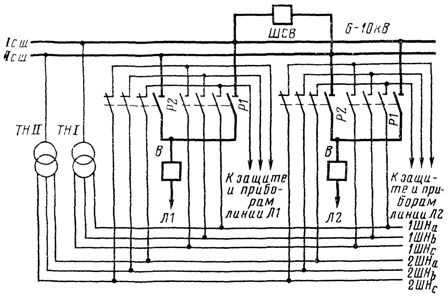
Rice. 7. Scheme of automatic switching using auxiliary contacts of disconnectors of secondary circuits of bus voltage transformers in switchgears for indoor 6-10 kV
In indoor 6-10 kV switchgear, switching is carried out through auxiliary contacts of bus disconnectors (Fig. 7). For example, when the disconnector P2 is turned on, the L1 lines of the voltage circuit are connected, on the one hand, to the voltage buses of the II bus system, through the auxiliary contacts of this disconnector, and on the other hand, to protection and devices of this line.
When transferring the L1 line to the I bus system, the disconnector P1 closes and the disconnector P2 closes. The L1 line voltage circuits are transferred via auxiliary contacts to the supply from the THI bus system. In this way, the power supply to the voltage circuits is not interrupted when the L1 line is switched from one bus system to another. The same principle is observed in operational switching of L2 line and other connections.
On lines 35 kV and above, connected to a double-bus system, the voltage circuits are switched using the contacts of the relay repeaters of the position of the bus disconnectors.When transferring primary connections to another busbar system, all voltage circuits are switched, including the earthed circuits of the main and auxiliary windings.
This excludes the possibility of combining the ground circuits of two VTs. This circumstance is important. As operational experience has shown, the combination of grounding points of different VTs can lead to disruption of the normal operation of relay protection and automation devices and is therefore unacceptable.
Rice. eight. Voltage circuits of the cabinet VT KRU 6 kV: 1 — voltage circuits, protective and other devices of the backup transformer c. n. 6 kV; 2 — signal circuit "Turning off the automatic circuit breaker VT"; 3 — Cabinet for voltage transformer KRU
In fig. 8 shows the voltage diagrams in the switchgear 6 kV VT cabinet s.n. Here the windings of two single-phase VT are connected in an open delta. The voltage transformer on the high voltage side is connected only by detachable contacts, and on the lower voltage side by detachable contacts and a circuit breaker, from the auxiliary contacts of which it is intended to transmit to the control panel a signal to turn off the circuit breaker AB.
During operation, it is very important to carefully monitor the reliable condition of the detachable contacts in the distribution and distribution cabinets and the circuits of the secondary voltage, operating current, etc.
Operating current circuits. Operating current has become widespread in electrical installations.
The performance of the operating current circuits must also ensure their protection against short-circuit currents.For this purpose, the auxiliary circuits of each connection are supplied with operating current through separate fuses or circuit breakers with auxiliary contacts to signal their disconnection. Circuit breakers are preferable to fuses.
The operating current is supplied to the relay protection and control breakers, as a rule, through separate breakers (separate from the signaling and blocking circuits).
For critical connections (power lines, TN 220 kV and above and SK), separate circuit breakers for main and backup protection are also installed.
Auxiliary DC circuits must have insulation monitoring devices that give a warning signal when the insulation resistance falls below a specified value. For DC circuits, insulation resistance measurements are provided at each pole.
For reliable operation of electrical equipment and their protection, it is necessary to control the availability of power supply for the working current circuits of each connection. It is preferable to monitor using relays that allow a warning signal to be given when the auxiliary voltage disappears.