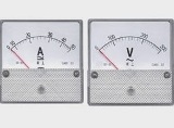
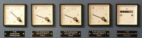
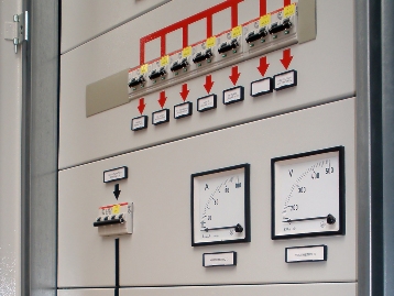
Measurement of current and voltage during operation of electrical equipment in industrial enterprises
 Measurements of current and voltage values in industrial enterprises provide control of the technological process of the main units, the established mode of operation, the quality and quantity of the received electricity, the state of insulation in networks with isolated neutral three-phase current.
Electrical measuring devices must comply with the current GOST, and their installation must correspond to PUE… Electrical measuring devices must meet the following basic requirements:
-
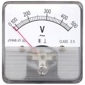
indicating devices must have an accuracy class of 1.0 — 2.5,
-
ammeters of substations, switchgear and electric motors may be of accuracy class 4,
-
accuracy classes of additional resistances and measuring transformers must not be lower than those specified in the table. 1,
-
the measurement limits of the devices must be selected taking into account the largest possible deviations of the measured parameters from the nominal values.
Table 1. Accuracy classes of additional resistance shunts and measuring transformers corresponding to the accuracy classes of measuring instruments. The accuracy class specified in parentheses is allowed as an exception.
Device class Shunt and additional resistance class Instrument transformer class 0.5 0.2 0.2 1.0 0.5 0.5 1.5 0.5 0.5 (1.0) 2.5 0.5 1.0 (3.0) 4.0 — 3.0
In the power supply systems of industrial enterprises, the following values of current and voltage are measured:
-
current with directly connected alternating current ammeters or by measuring current transformers,
-
voltage using direct AC ammeters or measuring current transformers,
-
voltage using direct AC voltmeters or via voltage measuring transformers,
The simplest way to measure amperage is to plug the ammeter in directly.

When connecting the ammeter directly, the following conditions must be met:
Aza≥ AzaR,
where Aza — the maximum measurement limit of the ammeter, A, Azp is the maximum operating current of the circuit, A,
Ua≥ Uc,
where Ua is the rated voltage of the ammeter, V, Uc is the rated voltage of the network, V.
When measuring current with a current transformer, the following condition must be met:
Ut.t≥ Uc,
where Ut.t — nominal voltage of the primary winding of the current transformer, V.
To maintain the accuracy class of the current transformer
To1≥ AzR/1.2
where To1 — rated current of the primary winding. Ah,
It1 = I,
where To1 — rated current of the secondary winding of the current transformer (usually 5 A), Aza — rated current of the ammeter, A,
Z ≈ R2 ≤ Z2n,
where Z2n is the nominal load of the current transformer in the accepted accuracy class, Ohm, R2 — nominal load, including the resistance of the contacts, connecting wires and the total resistance of the measuring devices connected to the current transformer. Om
If the number of measuring devices is large or they are significantly removed from the current transformers, it is necessary either to increase the cross-section of the wires or to use two current transformers that connect them in series.
See also: Measurement of currents and voltages in three-phase circuits
It is allowed to include ammeters for the difference in currents of two phases (in this case, the readings of the ammeter will increase by √3 times) or to connect ammeters to parallel-connected secondary windings of current transformers (in this case, the readings of the ammeter will be doubled ). This should be taken into account when re-calibrating or determining the scale division of the measuring device.
With a symmetrical load you should have one ammeter in one phase, with an asymmetrical load, an ammeter in each phase or one ammeter with a phase switch. In case of short current surges, ammeters with overload scale are provided and current transformers are selected according to the operating current.
See here for more details: Schemes for connecting ammeters through current transformers
The simplest way to measure voltage is to plug in the voltmeter directly and run the condition
Ut1≥ Uc,
where Ut1 is the nominal voltage of the voltmeter, V.
To extend the voltage measurement limits, additional resistances are used.
When measuring in high voltage AC circuits, use voltage transformers and meets the conditions:
Uv≥ Ut2,
where Ut2 is the rated voltage of the primary winding of the voltage transformer, V,
S2 ≤ Сн,
where Sn is the rated power of the transformer in the accepted accuracy class, VA, S2 is the rated power connected to the voltage transformer, VA.
To measure the voltage in a three-phase network using single-phase voltage transformers, it is enough to have two transformers (if the last condition is met) connecting them in an open delta circuit. One voltmeter with a switch is usually allowed.
For more information on how to connect voltmeters through voltage transformers, see here: Connection diagrams of measuring voltage transformers
In a high-voltage network with an isolated neutral, to control the isolation, it is desirable to have three voltmeters connected to the phase voltage, and the high and low voltage windings of the three-phase voltage transformer should be grounded. See also: Insulation monitoring in networks with isolated neutral.
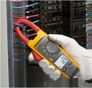 To quickly measure the current strength without breaking the wire and without disrupting the operation of the electrical installation, special electrical clamps allow.There are clamp-on ammeters, ammeters, wattmeters, phase meters and combination meters. Read more about them here: Electric clamp