Non-contact temperature measurement during operation of electrical equipment
 All electrical appliances work by passing an electric current through them, which further heats the wires and equipment. In this case, during normal operation, a balance is created between increasing the temperature and removing part of it to the environment.
If the contact quality is defective, the current flow conditions deteriorate and the temperature rises, which can cause a malfunction. Therefore, in complex electrical devices, especially high-voltage equipment of power enterprises, periodic monitoring of the heating of live parts is carried out.
For high-voltage devices, measurements are made by a non-contact method at a safe distance.
Principles of remote temperature measurement
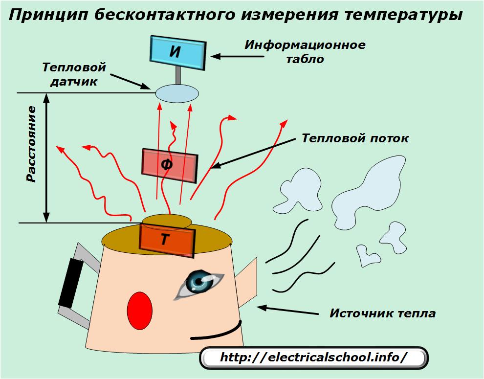
Every physical body has a movement of atoms and molecules which is accompanied by emission of electromagnetic waves… The temperature of the object affects the intensity of these processes, and its value can be estimated by the value of the heat flow.
Non-contact temperature measurement is based on this principle.
Devices for measuring temperature, which measure it by infrared radiation, are called infrared thermometers or their abbreviated name «pyrometers».
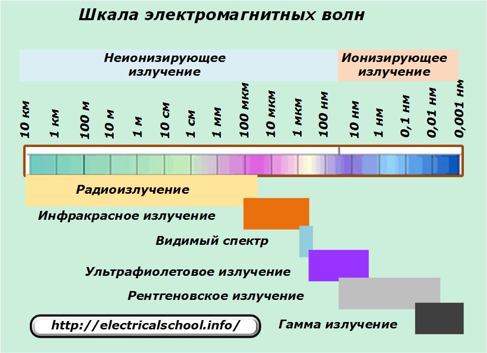
For their accurate operation, it is important to correctly determine the measurement range on the electromagnetic wave scale, which is an area of approximately 0.5-20 microns.
Factors affecting measurement quality
The error of pyrometers depends on a number of factors:
- the surface of the observed area of the object must be in the area of direct observation;
- dust, fog, steam and other objects between the heat sensor and the heat source weaken the signal, as well as traces of dirt on the optics;
- the structure and condition of the surface of the examined body affect the intensity of the infrared flux and the readings of the thermometer.
Does the third factor explain the graph of change in emissivity? of the wavelength.
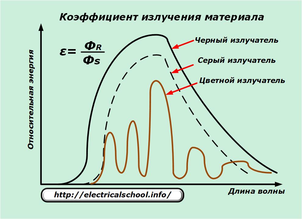
It demonstrates the characteristics of black, gray and color emitters.
The ability of infrared radiation Фs of a black material is taken as a basis for comparing other products and is taken equal to 1. The coefficients of all other real substances ФR become less than 1.
In practice, pyrometers convert the radiation of real objects into the parameters of an ideal emitter.
The measurement is also affected by:
-
the wavelength of the infrared spectrum at which the measurement is made;
-
temperature of the test substance.
How a non-contact temperature meter works
According to the method of outputting information and its processing, devices for remote control of surface heating are divided into:
-
pyrometers;
-
thermal imagers.
Pyrometer device
Conventionally, the composition of these devices can be presented block by block:
-
infrared sensor with optical system and reflective light guide;
-
an electronic circuit that converts the received signal;
-
a display that shows the temperature;
-
the power button.
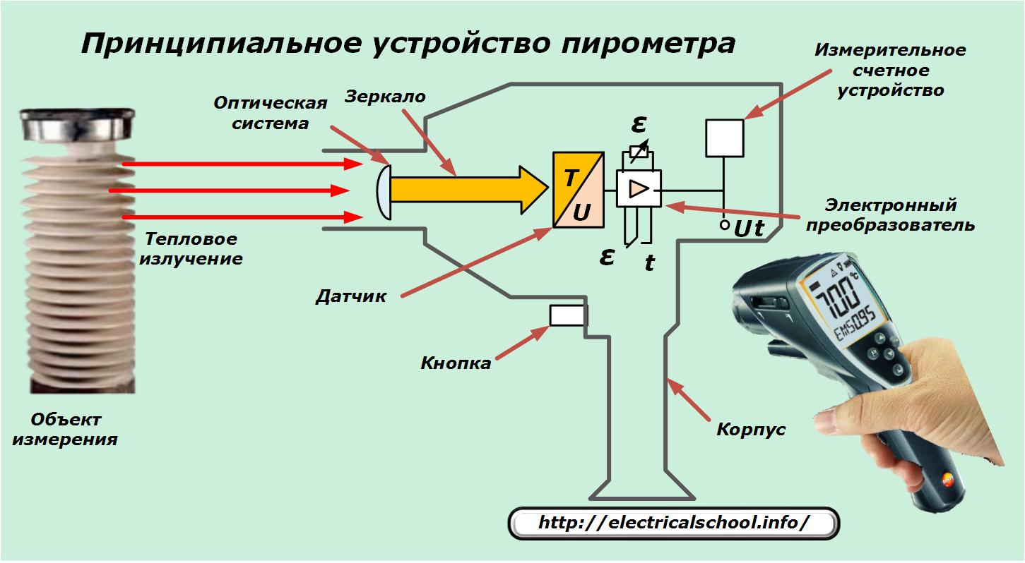
The flow of thermal radiation is focused by an optical system and directed by mirrors to a sensor for the primary conversion of thermal energy into an electrical signal with a voltage value proportional to the infrared radiation.
The secondary conversion of the electrical signal occurs in the electronic device, after which the measuring and reporting module displays information on the display, as a rule, in digital form.
At first glance, it appears that the user needs to measure the temperature of a remote object:
-
turn on the device by pressing the button;
-
specify the object to be investigated;
-
take a deposition.
However, for accurate measurement, it is necessary not only to take into account the factors affecting the readings, but also to choose the correct distance to the object, which is determined by the optical resolution of the device.
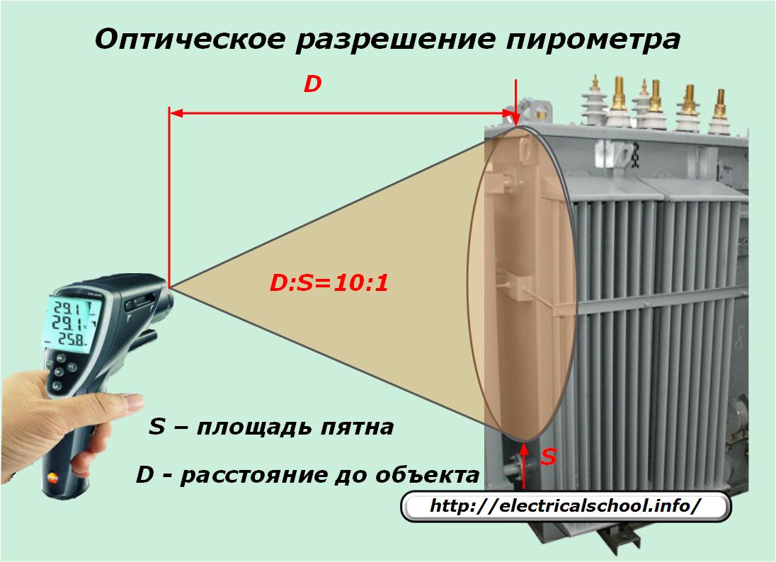
Pyrometers have different viewing angles, the characteristics of which, for the convenience of users, are selected for the relationship between the distance to the object of measurement and the coverage area of the controlled surface. As an example, the picture shows a ratio of 10:1.
Since these characteristics are directly proportional to each other, for accurate temperature measurement it is necessary not only to correctly point the device at the object, but also to choose the distance to choose the area of the measured area.
The optical system will then process the heat flux from the desired surface without considering the effect of radiation from surrounding objects.
For this purpose, improved models of pyrometers are equipped with laser designations that help direct the thermal sensor to the object and facilitate the determination of the area of the observed surface. They can have different operating principles and have different targeting accuracy.
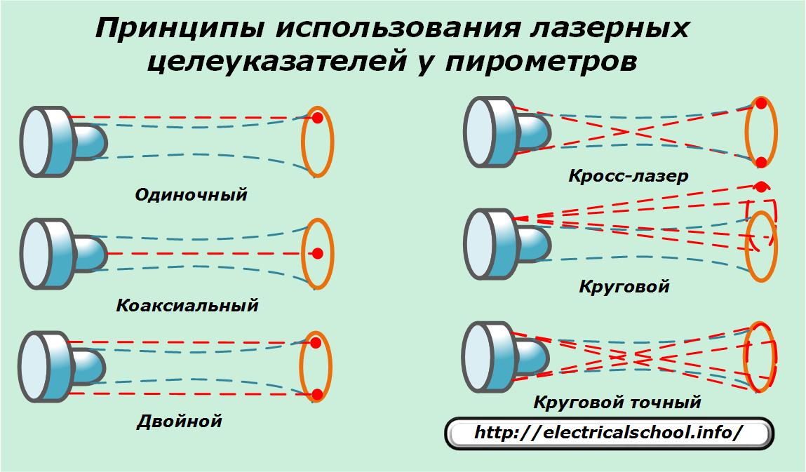
A single laser beam only approximately indicates the location of the center of the controlled area and makes it possible to determine its boundaries imprecisely. Its axis is offset relative to the center of the pyrometer optical system. This introduces a parallax error.
A coaxial method is devoid of this drawback — the laser beam coincides with the optical axis of the device and accurately indicates the center of the measured area, but does not determine its boundaries.
An indication of the dimensions of the controlled area is provided in the target pointer with a double laser beam... But at small distances to the object, an error is allowed due to the initial narrowing of the sensitivity area. This disadvantage is very pronounced with lenses with a short focal length.
Cross laser designations improve the accuracy of pyrometers equipped with short focus lenses.
A single circular laser beam allows you to determine the observation area, but it also has parallax and overestimates the readings of the device at short distances.
A circular precision laser designator works most reliably and is devoid of all the drawbacks of previous designs.
Pyrometers display temperature information using a text-numeric display method that can be supplemented with other information.
Thermal insulation device
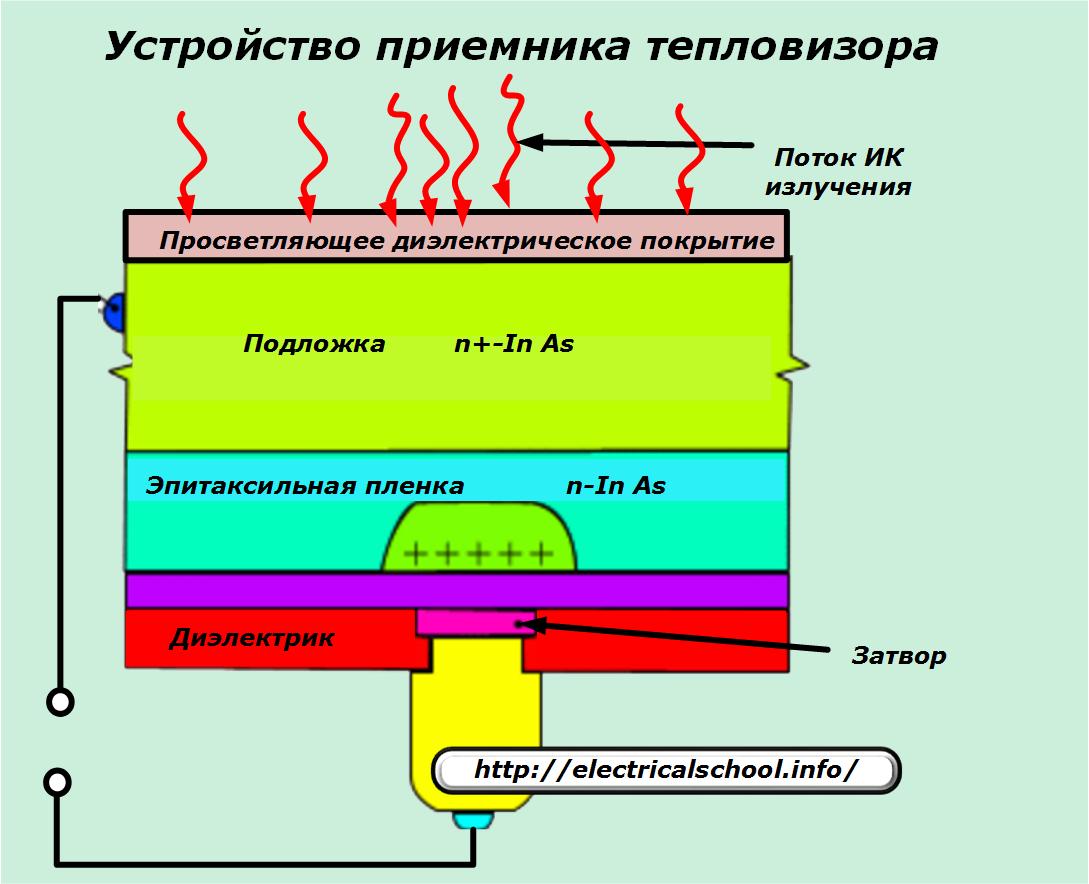
The design of these temperature measuring devices resembles that of pyrometers. They have a hybrid microcircuit as a receiving element of the infrared radiation stream.
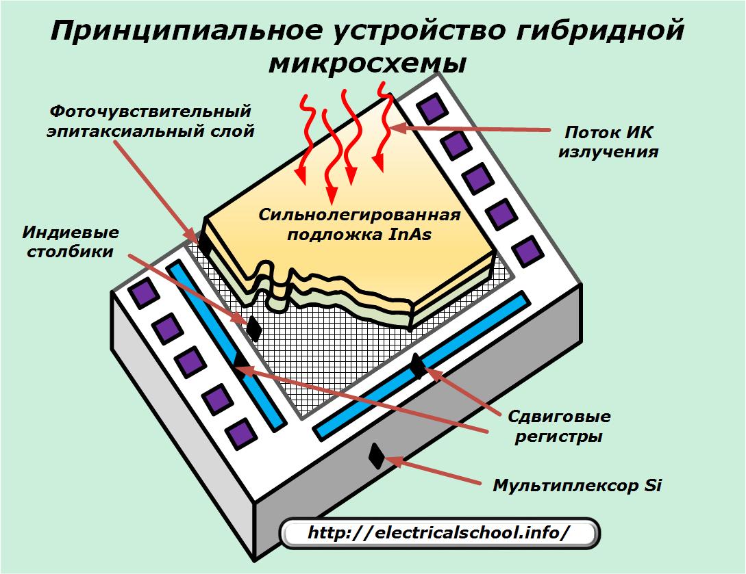
The device of the receiver of a thermal imager with a hybrid microcircuit is shown in the photo.
The thermal sensitivity of thermal imagers based on matrix detectors allows you to measure the temperature with an accuracy of 0.1 degrees. But such devices with high accuracy are used in thermographs of complex laboratory stationary installations.
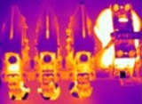
All methods of working with a thermal imager are performed in the same way as with a pyrometer, but a picture of electrical equipment is displayed on its screen, presented already in a revised color gamut, taking into account the state of heating of all parts.
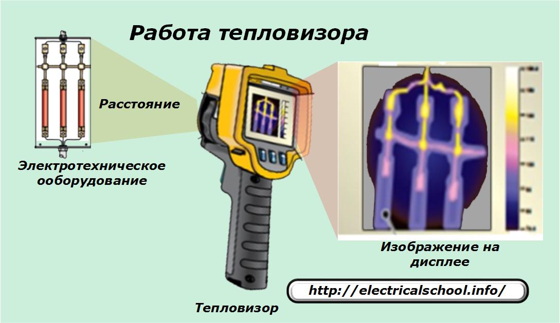
Next to the thermal image is a scale to convert colors to a temperature ruler.
When you compare the performance of a pyrometer and a thermal imager, you can see the difference:
-
the pyrometer determines the average temperature in the area it observes;
-
the thermal imager allows you to assess the heating of all constituent elements located in the area it monitors.
Design features of non-contact temperature meters
The devices described above are represented by mobile models that allow consistent temperature measurements in many places of operation of electrical equipment:
-
inputs of power and measuring transformers and switches;
-
contacts of disconnectors operating under load;
-
assemblies of bus systems and sections of high-voltage switchgear;
-
in the places of connecting wires of overhead power lines and other places of commutation of electric circuits.
However, in some cases when performing technological operations on electrical equipment, complex designs of non-contact temperature meters are not needed, and it is quite possible to cope with simple models installed permanently.
An example is the method of measuring the resistance of the generator rotor winding when working with a rectifier excitation circuit. Since large AC components are induced in it, the control of its heating is carried out continuously.
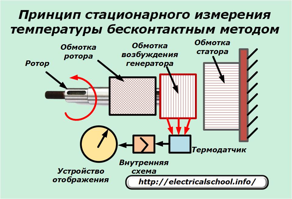
Remote measurement and display of temperature at the excitation coil is performed on a rotating rotor. The thermal sensor is permanently located in the most favorable control zone and perceives the heat rays directed towards it. The signal processed by the internal circuit is output to an information display device, which may be equipped with a pointer and a scale.
Schemes based on this principle are relatively simple and reliable.
Depending on the purpose, pyrometers and thermal imagers are divided into devices:
-
high temperature, designed to measure very hot objects;
-
low temperature, able to control even the cooling of parts during freezing.
The designs of modern pyrometers and thermal imagers can be equipped with communication systems and transmission of information through RS-232 bus with remote computers.